Objective
I want to design a tiny single packaged mains-powered temperature sensor. Possibly as a multi-chip module (MCM) on one small PCB board.
Constraints
The temperature sensor I plan to incorporate:
- Operates (Iq) between 1VDC, 10mA and 3VDC, 30mA
- It is a 65nm Samgsung fabraction process. So it is very small.
Power source:
around 220V mains powered (single-phase)
Operation without a secondary source (batt, bulk cap, et. al.) desired to minimize size.
The efficiency demanding is just >10% and that is enough for me.
Ideas now
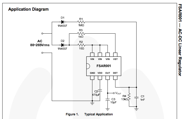
I was intended to design my power converter into a small chip, thanks alot for people's suggestions . I think about charge pump, and different IC modules, the RF powerharvesting, and the possibility for implementing such a device on nm Si process. Above all, microchips that can convert 220V ac to low dc is big-size for me, and also have lots big caps around module; charge pump from Olin's idea, I dont think I can design diode that can support high-voltage on chip, if not on chip, it will be big size(I think); for powerharvesting, I did some research before, and honestly it is good, but RF energy is not very solid, and there are some limitations about the distance. So I go back to the original ideas how to convert voltage. Hope your guys can check if they are right. I will use some regulating stuff(off chip) to regulate the voltage at last, so i just wanna check if the thoughts are right.
1> Linear with the resistors. Input 220Vac to the two resistors,one is 1Mohm, the other is around 10Kohm,figure below:
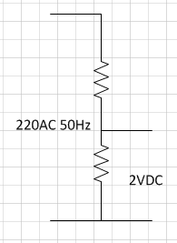
I know the efficiency is verylow, about 1%, so I drop it. But it is my earliest idea.
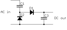
2> linear with the capacitor. Since the first way efficiency is so low, I wonder can I use two capacitors to replace the resistors, (figures below) one cap is 1pf, the other is 10fF (the exact values are not certain).
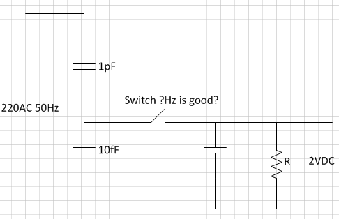
also I wanna design the big capacitor on my pcb board by myself like figure below,so I can mini-size. If the cap value is not big, I can design it on chip.
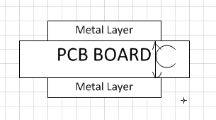
First I dont know if the fundamental of circuit (the first figure) will work or not, because I never see this before, but as I know, I hope it works. Assume it works, how to design it exactly ( I mean how to design the cap value properly and how to choose the switch frequency properly).
3> The conventional linear isolating converter:
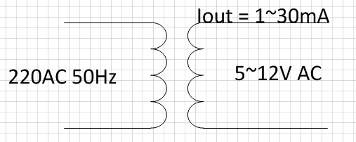
My question is, in this conventional way, the output current in other designs usually needs big, so the transformer is big, but I just need it very small(1mA~30mA), so according to your view, how big it will be, I know little about transformer design. the voltage ratio is 45:1, and the current is 1:45, how many coils on both sides are good ? How big it will.
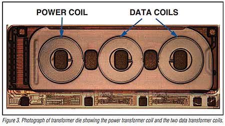
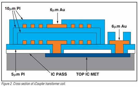
if the transformer above is not so big, Furthermore, my design method for the transformer is improved, and I wanna design transformer on PCB board by myself, like figures below:
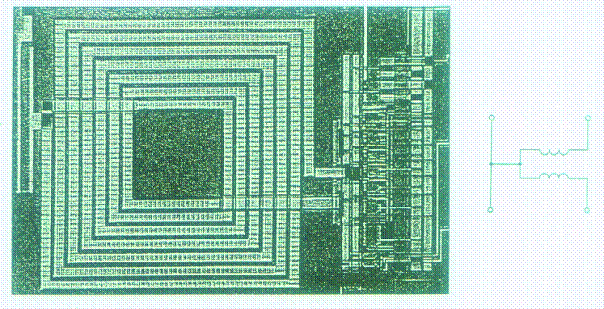
in my first figure, I just use one stage transformer, if size is big to design 220V-5V converting, maybe I can design two or more stages to convert like 220V-48V-5V. I hope the transformer (each stage, hope one stage is enough) is less than 1cm×1cm. If that is possible, I WILL do it. And I think the efficiency is good, and also safe.
Above all, I want to improve my design in the No 2 and No 3 method, but I dont know if my thoughts are right or not. Ready to get judgement now.

