3
\$\begingroup\$

I have been reading and watching TI's material on EMI input filter design, and I have a few questions.

My basic question is "How do you select the component values for your EMI input filter?" The specific application I am designing a filter for is a 24V, 120W flyback converter in the consumer electronics market.

Next, I will detail what I have learned.

The input EMI filter has 4 main components: Common-Mode choke, X-Cap, Y-Cap, and Filter Inductor.

The CM Choke and Y-Caps are in charge of attenuating the common-mode noise, while the Y-cap and Filter inductor are in charge of attenuating the differential-mode noise.

I believe that the common-mode choke is first selected based on its attenuation curve and what you think the the trouble frequencies will be. You then verify this choice experimentally.

I believe the X-Cap choice is based on power consumption and power factor (according to post linked below)?

X capacitor selection for SMPS power supply

I will admit that I am not sure how to calculate the power consumption of a capacitor in this context.

TI's application notes on the filter inductor put it in the context of a CLC filter, which is confusing because I thought we chose the input/smoothing capacitor value based on the input power and not the required attenuation.

My design (and the reference designs I am using) does not feature any Y-Caps because the line cord does not have an earth-ground connection prong.

Best,

Basically, I just need some help on how to initially determine the values for these components.

\$\endgroup\$
3
  • \$\begingroup\$ Beforehand, you need the current signature of your converter operated in nominal conditions. This signature can then be used to determine the amount of harmonics and how much you shall attenuate them to pass the standard with margins. This is for conducted differential mode filtering. Prediction and compensation on a computer is usually doable, provided you have models including parasitics. You can have a look at an old app note I wrote. For CM mode, it is almost impossible to predict and you'll have to debug the first prototype. \$\endgroup\$ Commented Jan 14, 2021 at 11:57
  • \$\begingroup\$ RGB Engineer, are you done with this question now or do you still need some help? \$\endgroup\$
    – Andy aka
    Commented Jan 27, 2021 at 9:13
  • \$\begingroup\$ Hello, I am still formulating my next question. \$\endgroup\$ Commented Jan 27, 2021 at 9:26

1 Answer 1

7
\$\begingroup\$

The specific application I am designing a filter for is a 24V, 120W flyback converter in the consumer electronics market.

The very first thing I would do is simulate the circuit in order to understand the current consumption and harmonics in the worst case loading scenario. In other words: -

$$\boxed{\text{Don't try and design any EMC filter values until you have this buttoned-down.}}$$

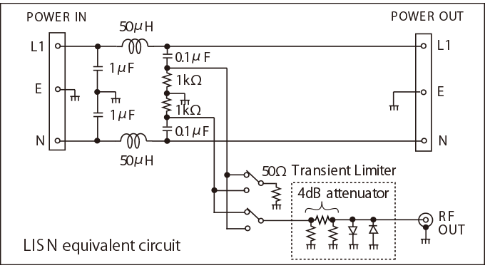
Then, still using a simulator, I would mimic a feed cable of the appropriate length terminated in a LISN connection so that I can actually get to the noise/interference voltages that might actually be produced by the switcher. LISN example: -

enter image description here

Picture from this website. At this point I have to mention this: -

$$\boxed{\text{The above is an attempt to establish conducted emission values}}$$

Having said that, pretty much most of the radiated emissions are going to be emitted from the feed cable so, it's not such a bad thing to only concentrate on conducted emissions.

Regards the LISN and the feed cable, you will have to decide what the set-up is and, this is determined to a large extent by what conducted emission standard you are trying to meet. I can't tell you what this is so you need to do your homework.

$$\boxed{\text{Decide on the standard and read what LISN it uses}}$$

You will also need to evaluate the feed cable and estimate to what extent it may not be perfectly balanced with respect to earth. You have to do this in order to generate conducted emissions because, if you didn't do this then, in a simulator, because the cable would appear to be "perfect", there would be zero common-mode conducted emissions and that would be pointless to pursue: -

$$\boxed{\text{So, model your power feed cable with attention to detail}}$$

You actually might need to do some physical testing on a cable to determine how imbalanced it might be relative to earth.

The actual easy bit (that takes very little time if done properly) is adding whatever common mode filters and chokes are needed to reduce the emissions to a reasonable level.

However, do not skimp on modelling the CM chokes at this point; do some research on what resonant frequencies the CM choke may have and thoroughly satisfy yourself that your model is good.

My design (and the reference designs I am using) does not feature any Y-Caps because the line cord does not have an earth-ground connection prong.

Well, in that case you have no ideal place to connect the CM mode capacitors and you will always sail close to a pass/fail if you do not take great care reducing the harmonics of current consumed through live and neutral. Even more reason to simulate.

$$\boxed{\text{This is how I would do it}}$$

But, there's no guarantees you will pass your conducted emission test because reality is never the same as a simulation. However, not simulating isn't really a viable option these days because you will definitely significantly improve your chances of getting close to a pass by doing so and, pretty much, all from the comfort of your desk.

\$\endgroup\$
5
  • \$\begingroup\$ "The actual easy bit (that takes very little time if done properly) is adding whatever common mode filters and chokes are needed to reduce the emissions to a reasonable level." This is the part I do not understand. Let's say I have done all of the things you have listed above, how do I select the component values (inductance, capacitance) for each filter component? \$\endgroup\$ Commented Jan 14, 2021 at 12:25
  • \$\begingroup\$ You do it within the simulator to try and minimize the spectrum of current fed onto the cable so that the LISN output indicates something like a "pass". Then you try and choose off-the-shelf parts that might suit and mimic these in the simulator taking into account what the data sheets say about parasitic elements @RGBEngineer. \$\endgroup\$
    – Andy aka
    Commented Jan 14, 2021 at 12:29
  • 1
    \$\begingroup\$ $$\boxed{\text{Good Effort Andy. Experience with a simulator, Network Analyzer test method, Sig Gen and SA is required then an understanding of saturation in the ferrite and thermal effects. is essential}}$$ Experience is gained faster by Reverse Engineering existing solutions for EMI and PLT immunity with an understanding of kV impulse and emission requirements. \$\endgroup\$
    – D.A.S.
    Commented Jan 14, 2021 at 13:42
  • 1
    \$\begingroup\$ Thank you @TonyStewartSunnyskyguyEE75 - what a nice box you made! \$\endgroup\$
    – Andy aka
    Commented Jan 14, 2021 at 13:44
  • \$\begingroup\$ @RGBEngineer if you are done with this please consider formally accepting it or, raise a new comment for clarification. \$\endgroup\$
    – Andy aka
    Commented Jan 16, 2021 at 12:40

Your Answer

By clicking “Post Your Answer”, you agree to our terms of service and acknowledge you have read our privacy policy.

Not the answer you're looking for? Browse other questions tagged or ask your own question.