You could have less trouble and better control if you charge with a dedicated analog circuit, as I answered in another post (see ahead).
However, trying to answer strictly what and how you asked, you could achieve by several methods: From an accurate and more complicated way, or the simpler and discrete ones. The simpler could be to use some current-limited sets as {LM317 + NPN + R.sense} to drive down the current at different set values. Let’s say two assemblies adjusted at 1A, a third one at 0.5A. Selecting them in parallel could enable currents from 0.5 to 2.5A.
See also the second diagram I posted in the following link here Q1 and R.cl, and the explanation preceding that circuit about how it works.
My preference is to use this 3-stage charger, that is a good and safe way to charge a SLA battery. I already built several of these chargers, based in the first picture of that post, with the modifications/upgrades I detailed there.
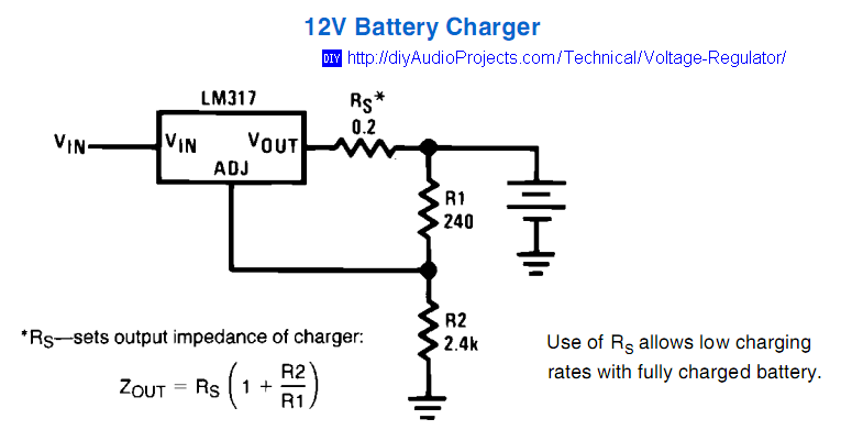
An intermediate way could be to add a resistance in the output terminal as 0.2Ω to 0.5Ω and benefit from the voltage and impedance multiplication at the output of the LM317, as I illustrated in this picture (source already marked inside):
 So, for a 12V Charger the equivalent R.out impedance of the charger would be around 2Ω to 5Ω, respectively.
Some brainstorm on a not so complicated way, using simplified control setup with a microcontroller,as you intend: if you combine an adjustable V.ref (for instance generated by a PWM +RC) to shift the “reference-ground” of the LM317s (in parallel and with R.out), you could either adjust the voltage or the current. This control would be at digital level, with algorithms in the microcontroller (as an Attiny85 or Arduino). The R.out would just enable a smoother current variation when you vary the voltage, and vice-versa. Your algorithm is the one who will determine if this crude “microcontrolled power supply” would prioritize Constant Voltage (CV) or Constant Current (CC), to your set points and charging profile. If not properly designed, the control will be slow or could overshoot, but in a worst case voltages and currents would be contained by the “hardware” circuitry around the LM317; and a SLA battery will forgive transitory hunts for the set-points, so at least it could be a fun experience.
Voltage dividers before and after the power resistor could sample the voltages and calculate the differential (proportional to current) in a voltage range that AD channels of a microcontroller could read, for instance.
Just be attentive of minimum and maximum common-mode voltages, unexpected voltage swings, also if battery is connected reversed, or when the power source still powered off. Current limiting resistors and shunting diodes might be helpful to protect the AD ports and other circuitry.

