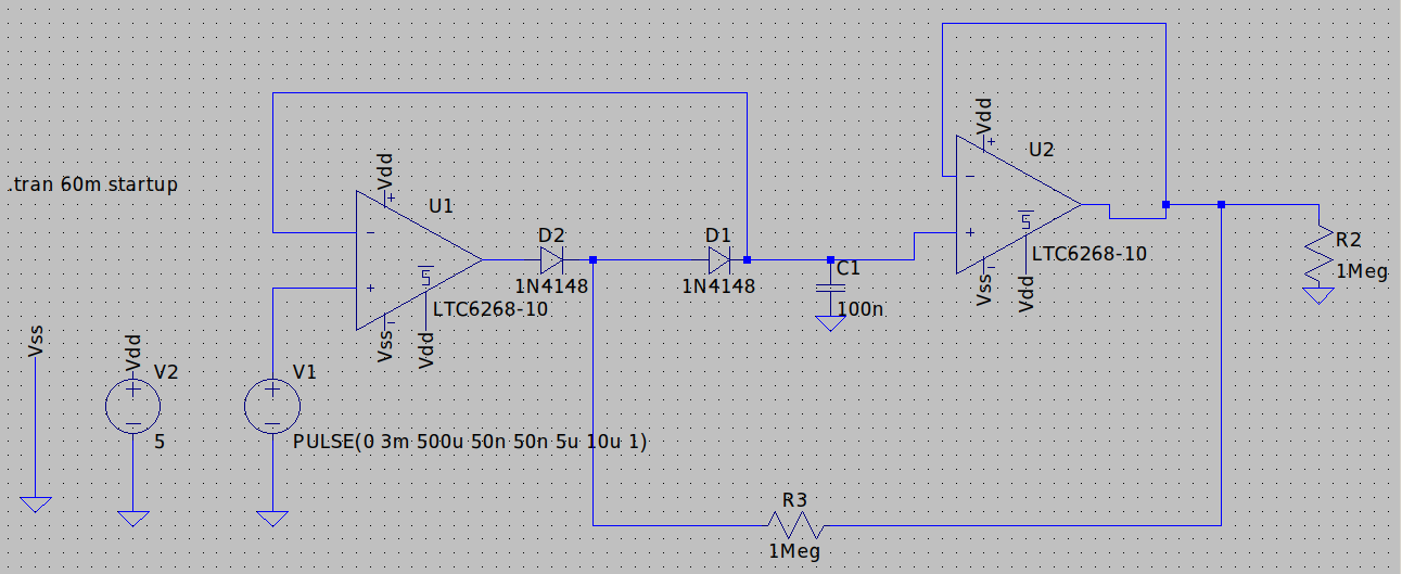
So I made this precision peak detector circuit (with reference from EEVblog's video and experimenting with the resistor/capacitor values), with which I want to measure the peak amplitude of a single pulse of width 5us (50ns each rise/fall time at best and 155ns/90ns rise/fall time at worst) and the amplitude is variable and can be within 3mV to 3V. I would like the peak-detector to hold the voltage level for a sufficient amount of time (in this case around 60ms, although I have simulated up to 3s with the same result) without degrading the voltage level too much (a maximum of 1-2mV degradation over 60ms is acceptable for me).
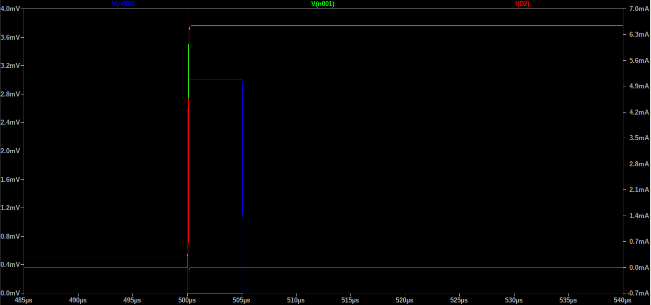
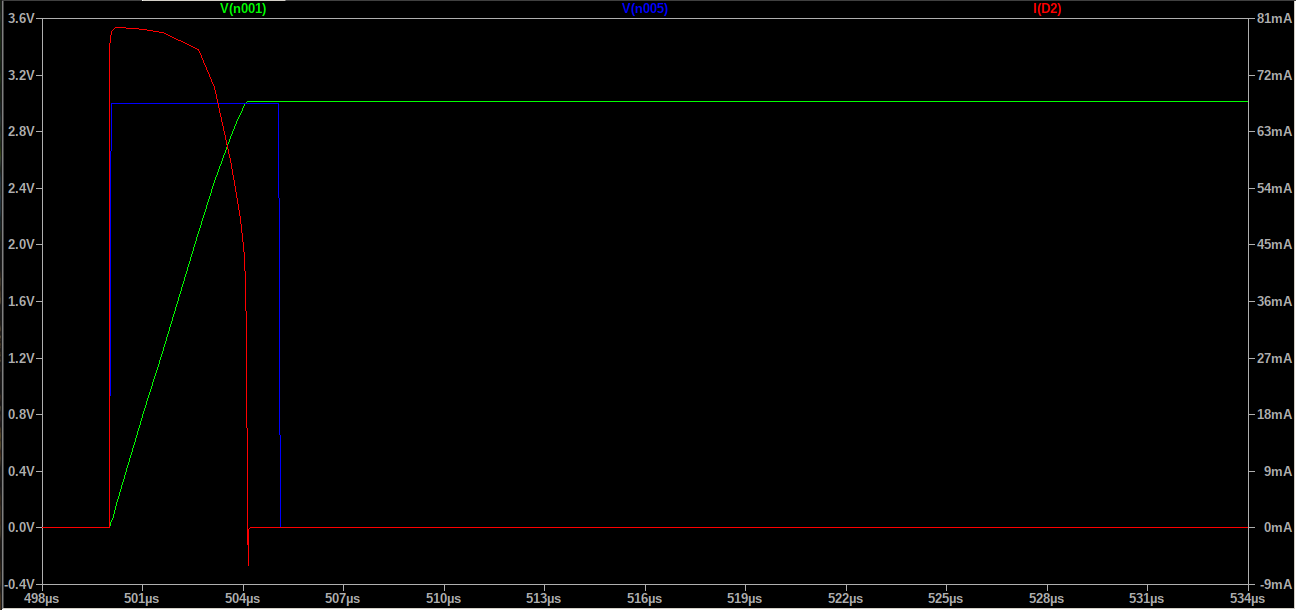
So the result of the above circuit looks good in the simulation. When testing for the extremes I see the following (pics below). Here Green is the final output (voltage at R2), Red is D2 current(essentially to show the peak current the opamp can handle), Blue is the input pulse (V1):
For 3mV pulse, here are the results:
 As, you can see there is a slight offset of around 0.6mV, which is acceptable for me as long it is fairly constant over all my measurements.
For 3V pulse, here are the results:
 Here the peak current in diode D2 (or as I think is a measure of maximum current required from the opamp (U1) is around 79.6mA which is right below LTC6268-10's typical peak output current rating of 80mA.
R2 is basically modeling the input impedance of an ADC which I'll directly connect at the output of U2. I chose LTC6268-10 because of its low input bias current which 'should' help the capacitor to retain the voltage (in this double diode configuration as per the video) for a long time. I would also be using a low leakage analog switch/mux to discharge the capacitor (short it to ground) after I sample it using my ADC.
I need to be as sure as possible that this circuit would work as in simulation (or at least, close enough) before I put it in a PCB.
So my questions are:
Do you find any obvious mistakes that I am making here with my component selection (or their values) or the circuit itself? or do you suggest a better circuit to achieve my goal (of measuring peak voltages of a single pulse with an ADC)?
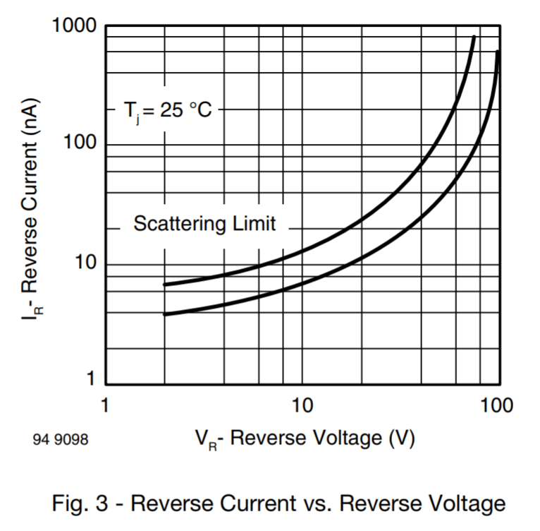
In the simulation the capacitor is holding the voltage very very well, which is good but I am thinking if there are any other ways the capacitor could get discharged (in the real world), and what should I take into consideration? Is there a specific type of capacitor, I should go for?
Is there a ready-made peak detector IC available already that would perform better than this circuit? I am not looking for S/H IC because I would require precise trigger timing to sample at the middle of the pulse.
Since I'll be using SMD components, if you would like, you may suggest anything important that I need to know regarding using SMD diodes, capacitors, etc for this particular circuit.
Side note: If the requirements are too high then I may be inclined to reduce the hold time (currently 60ms) to 6ms depending on the suggestions if that results in a simple circuit.
Thank you so much for reading my post.


