9
\$\begingroup\$

I've used PIC16F877 (datasheet) for several projects. For a single external pin change interrupts, you can use PORTB0 interrupt. But now I need to support 8 independent external pin change interrupts, in a single circuit.

In the datasheet it says there are 15 interrupts in PIC16F877, but i guess those are counted including timer overflow interrupts etc... which are useless in this case.

This is what datasheet say about INTCON register.
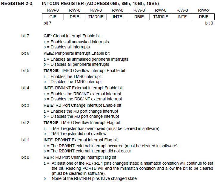
enter image description here

Can I have 4 independent interrupts using bit0, RBIF? It represent change in PB7:PB4. How can I identify which pin changed, is it by reading the port value in the interrupt routine?

Even I get positive answers to above, I need 8 interrupts? of course I can still use INTE, for PORTB0 change. Then 4 + 1 = 5, but what about other 3? (However being all the 8 interrupt events are of same type, the 4 + 1 + 3 = 8 thing seems ugly, isn't it?)

There's no other heavy tasks expected from the micro-controller other that monitoring 8 pins. (Talking about the other tasks, it'll have to maintain a set of separate counter variables and frequently transmit about 4 bytes to PC serially)

Any suggestions are welcome. Even if it's about changing the micro-controller for more suited one (but uh.. don't tell me to go away from PICs).

\$\endgroup\$
9
  • 2
    \$\begingroup\$ Without using interrupts, may be you can monitor the pins in the main program. But that's not perfect though. As an alternative, you can go for Arduino. Though it's not PIC, it's pretty simple, you'll easily understand as you are already familiar with PICs. \$\endgroup\$
    – Anubis
    Commented Jan 15, 2013 at 4:59
  • 1
    \$\begingroup\$ If you use the RBIE interrupt you could just buffer the previous value each time and an XOR to find what's changed. Should be pretty quick to execute. \$\endgroup\$
    – PeterJ
    Commented Jan 15, 2013 at 4:59
  • \$\begingroup\$ @PeterJ i didn't quite understand that. Buffer which value? \$\endgroup\$ Commented Jan 15, 2013 at 5:02
  • \$\begingroup\$ @PeterJ great! waiting... \$\endgroup\$ Commented Jan 15, 2013 at 5:05
  • 1
    \$\begingroup\$ One way is to use an external 8-input gate (such as the 74LS30 in the old days) to combine the external signals onto one interrupt pin. As the 74(HC)30 is a NAND gate you would need all the inputs high in the quiescent state - they would also need to be connected to port pins so you could identify which interrupts were active by reading the port. \$\endgroup\$
    – user16324
    Commented Jan 15, 2013 at 11:33

3 Answers 3

3
\$\begingroup\$

This is C pseudo-code to explain one idea. It uses and exclusive OR to work out which pins have changed and will call your different handlers within the one RBIE interrupt. Depending on how critical the application is you may want to check how the PIC handles situations such as a port changing while the interrupt is executing to make sure you won't miss any events.

int old_port_b;

void isr_handler()
{
    int new_port_b, changed_pins;
    new_port_b = read_port_b();
    changed_pins = new_port_b ^ old_port_b;
    if (changed_pins | 1)
        rb0_hander();
    if (changed_pins | 2)
        rb1_hander();
        // ... etc
    old_port_b = new_port_b;
}

int main()
{
    old_port_b = read_port_b();
    enable_interrupt();
}
\$\endgroup\$
5
  • \$\begingroup\$ I get it, thanks! but that's not the exact answer i'm looking for. That way, you can monitor RB7:RB4 4 pins only. But I'm asking for a way to monitor 8 pins. any suggestion? \$\endgroup\$ Commented Jan 15, 2013 at 5:12
  • \$\begingroup\$ I guess there's a reason you can't use RB0 - RB7 the above should work for? Otherwise I can't really think of a way, if trigerring the code quickly isn't vital you could use the above style of code in a timer interrupt (or just the main loop). \$\endgroup\$
    – PeterJ
    Commented Jan 15, 2013 at 5:15
  • \$\begingroup\$ For that PIC, if you need to use interrupts to do this, the XOR trick on RB4:RB7, and four interrupts for the RB0:RB3 is the way to go. If you don't need the interrupt, just poll the whole port in your code, or use a timer interrupt to handle the polling if you need a hard sample rate \$\endgroup\$ Commented Jan 15, 2013 at 14:05
  • \$\begingroup\$ and four interrupts for the RB0:RB3? PIC16F877 don't support any interrupts for RB1:RB3, eh? \$\endgroup\$ Commented Jan 16, 2013 at 4:26
  • \$\begingroup\$ I'd missed that in the datasheet, I was assuming it covered the whole port. But I saw your other comment about once per second so I think you'd be better just running this in your main loop. With interrupts you'll need to take care of variables updating at any point during execution and how to handle pin changes while the interrupt is running. It really sounds like it will just complicate it for no real gain. Only exception I could think of is if you wanted to use wake from sleep on interrupt, in which case you'd need to hardware MUX them. \$\endgroup\$
    – PeterJ
    Commented Jan 16, 2013 at 5:20
1
\$\begingroup\$

That part only has 4 pin-change interrupts and a few others you can set up on selected edges. One strategy would be to detect a change in the 8 bit value externally, then interrupt on the mismatch. That gets messy in hardware, but will so exactly what you want.

The important parameters that you haven't stated are how fast you need to respond to a pin change, and what minimum time will a pin change persist for it to be valid. Depending on the answers, you could poll based on a regular interrupt in firmware. The 16F877 can run at 5 MHz instruction rate, and checking for a change would only take a few instruction. Let's say you set up the interrupt every 50 instructions. That would leave a good portion of the processor time to the foreground code. The interrupt rate would be 100 kHz and the period 10 µs. Of course the foreground code then still needs to see the change flag and do something about it, so the response time will be more than 10 µs, but you haven't said anything about what you need to do when a change is detected. If this just needs to respond in human time, then you can run the interrupt a lot slower.

\$\endgroup\$
3
  • \$\begingroup\$ Sorry about the missing details. As the expected response rate once per second will be sufficient. When a pin change (only one edge, say rising) is detected, a counter (variable) has to be incremented. In the main loop, it has to monitor the counter values and when one gets higher than a certain value, four bytes has to be transmitted via USART to PC. Then reset the relevant counter value to zero. Simple as that. I guess the polling option will go fine right? \$\endgroup\$ Commented Jan 16, 2013 at 4:42
  • 2
    \$\begingroup\$ Once per second! So what's all the agonizing over interrupts for? This is easily done with polling periodically. What's the problem then? \$\endgroup\$ Commented Jan 16, 2013 at 13:00
  • \$\begingroup\$ um...i though it'll be best since there are 8 of them and also, the response can't be predicted (but that value can be assumed to be the minimum). hey! people can do mistakes, right.. :( \$\endgroup\$ Commented Jan 17, 2013 at 4:31
1
\$\begingroup\$

You may use 8-input gate NAND as mentioned by @Brian Drummond to rise an interrupt over INT pin and also connect your interrupt sources to 8-Bit Parallel-In/Serial-Out Shift Register like "74HC165N", so then you will need to just read the data from that Shift Register after interrupt rised and that will give you the information about your actual interrupt source ... it is may be not the fastest way, but easy to expand and will use not more then 5 pins, and if you add address controlling system (MUX, LATCH ,...), then you will need only one pine for interrupt notification and other pins may be reused at different time for different resources ;)

\$\endgroup\$

Your Answer

By clicking “Post Your Answer”, you agree to our terms of service and acknowledge you have read our privacy policy.

Not the answer you're looking for? Browse other questions tagged or ask your own question.