0
\$\begingroup\$

I'm trying to understand brushless dc motor control via field orientated control, I'm watching this video here : https://youtu.be/YPD1_rcXBIE?t=588

Here we have the "Inverse Clarke/Park" algorithm, being computed on some microcontroller, or special hardware (Digital signal processors?). The output is the three phase voltage to be sent to control the motor stator currents. I believe.

I thought the three phase inverter can only turn on and off the motor coil pairs, but can it output, say a "decimal voltage", to turn it on and off only slightly?

I'm a beginner at learning electronics and motor control circuits... Please correct me when my understanding is wrong.

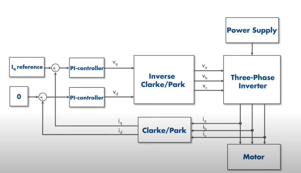
block diagram

\$\endgroup\$
2
  • \$\begingroup\$ The pwm forms an 'average' voltage - ie 50% duty cycle = 50% of bus voltage, 10% duty cycle = 10% bus voltage and so on. The duty cycle is varied by a sine table to approximate a sine wave. The inductance of the windings also serves as a low pass filter so whilst the pwm signal is on/off, the actual current is smoothed by the inductance. \$\endgroup\$
    – Kartman
    Commented Mar 17, 2021 at 11:25
  • \$\begingroup\$ It's a conceptual number. How it's represented - voltage, PWM duty cycle, or a binary word in a DSP, is irrelevant. Convert it to the form you need ... at the FETs, that will be a PWM duty cycle. \$\endgroup\$
    – user16324
    Commented Mar 17, 2021 at 12:10

2 Answers 2

1
\$\begingroup\$

I think I understand your confusion. The diagram shown above is misleading by stating Va, Vb, and Vc is coming out of the park and clarke transform! The decimal value that comes out of the park and clarke transform is not a voltage! It is a control signal from 0 to 1 that controls the duty cycle of the inverter, where 1 would mean applying full voltage to the motor and 0 means applying no voltage. These control signals will then be used to switch on and off transistors at high speed, synthesizing the sinusoidal voltages that feed into the motor.

The park and clarke transform is a technique used to linearize the dynamics of the motor, its just matrix math, and not power electronics.

\$\endgroup\$
1
  • \$\begingroup\$ Yes that explains it! Thank you! \$\endgroup\$
    – C Lu
    Commented Mar 26, 2021 at 0:55
0
\$\begingroup\$

The Clarke-Park transform and its inverse convert 3ph to quadrature polar (sin+cos) signals and visa versa so that FOC can be implemented easier for controlling no load speed with voltage and regulating torque with current. The average voltage and current is modulated by a high frequency duty cycle to regulate speed depending on the load and motor capacity.

Visual explanation. https://www.mathworks.com/solutions/power-electronics-control/clarke-and-park-transforms.html?back=https%3A%2F%2Fwww.google.com%2Fsearch%3Fclient%3Dsafari%26as_qdr%3Dall%26as_occt%3Dany%26safe%3Dactive%26as_q%3DWhat+is+the+Clarke-Park+transform+for+FOC+motors%26channel%3Daplab%26source%3Da-app1%26hl%3Den

\$\endgroup\$

Your Answer

By clicking “Post Your Answer”, you agree to our terms of service and acknowledge you have read our privacy policy.

Not the answer you're looking for? Browse other questions tagged or ask your own question.