1
\$\begingroup\$

This is my first time here so sorry for any wrong formatting.

I am currently creating a project where I will run my wall with 10 meters of addressable LED strip (Made up of 2 x 5 meters rolls). I have two 20 amp, 5 V power supply for the project. After calculating 60 LEDs/meter at 5 V it would consume around 18.8 W/meter meaning that at 10 meters it would be 188 W, 5 V = 37.6 amps.

I searched a lot but don't have the necessary understanding of electrical engineering to safely conclude what I am going to do. Below I made up two different scenarios which I could wire up, my two questions are:

  1. Are my scenarios safe? / Would they work?
  2. Is there any recommendations or changes to my schematic?

To control the addressable LEDs I am using a microcontroller board called NodeMCU, which would acquire 5 V from the power supply and send the data signal through the LEDs.

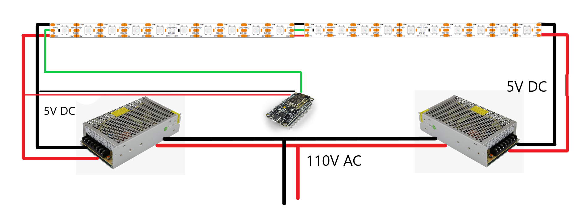
Case 1

none

For the first case I would have each power supply connecting at one end of the strip and both strips connected together in the middle for power and data, meaning I would not have any voltage drops. The NodeMCU would acquire 5V from the first power supply and send data through one end.

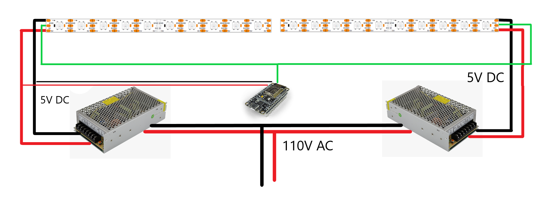
Case 2

none1

Case 2 is similar to Case 1 but the only difference is that there wouldn't be a connection between both strips and the NodeMCU would transmit data at both ends otherwise one strip wouldn't receive data.

I appreciate any opinions and suggestions to my schematic, thank you!

\$\endgroup\$
3
  • \$\begingroup\$ the data flow in a strip is directional. You can't "feed in data" on both ends. that's not how any of this works! \$\endgroup\$ Commented Mar 17, 2021 at 21:22
  • 1
    \$\begingroup\$ @MarcusMuller second schematic two strips are not connected at middle. \$\endgroup\$
    – user263983
    Commented Mar 17, 2021 at 21:26
  • \$\begingroup\$ No, but if data flow is from left to right on the left strip then it will be left to right on the right strip. You've shown black at the top on both sides so you haven't reversed them. \$\endgroup\$
    – Transistor
    Commented Mar 23, 2021 at 17:56

2 Answers 2

0
\$\begingroup\$

Are my scenarios safe? / Would they work?

No the first one is not safe

Yes the could work under ideal conditions, if the supplies were balanced and the strip were balanced and the cables were balanced then this could work. This balancing is probably not possible in real world conditions.

What is more likely to happen is this: Any difference in voltage will manafest itself as large currents, lets say the led strip was 1Ω across the strip, an 0.1V difference would generate 1Ω/0.1V = 100mA of current that would be wasted as heat in the cable. Many supplies are not matched and are less than 0.1V (especially cheap ones). An 0.5 difference could be 500mA and so on. The current could be so large it could burn out a cable or the traces on the LED strip.

Case 2 is probably OK, but you will also need to ground both supplies together, otherwise the digital of the 2nd supply will have no reference and no way for the return current to get back to the NodeMCU.

You may also want to consider a buffer IC to digitally buffer the digital from the NodeMCU, check the fanout on the LED strips. If they pull too much current on the digital pins than the NodeMCU GPIO's can source then you will need a buffer.

\$\endgroup\$
0
\$\begingroup\$

TLDR: Don't even try scenario 1. It will damage one of your supplies and potentially overheat the strip. Fire hazard! Scenario 2 is safe but you will need common ground (i.e. common reference) for both supplies and your controller board

Long Explanation: Whenever there's doubt about something, always simplify your diagram. At the end of the day with know the logic just controls the LEDs and does not carry a whole lot of power (i.e. no safety concern). Your safety concern is in your power supplies

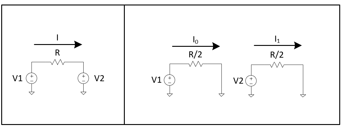
The problem lies on having your power supplies in parallel only separated by the strip. Ideal power supplies will put out a voltage independent of the current that the load demands. Therefore, it there's a mismatch in the voltage levels, one of the power supplies will be required to sink that current. As you may know, power supplies are good at sourcing current, but not sinking currents.

Lesson: Never, literally never, connect two supplies in parallel.

Scenario 1 - Left, Scenario 2 - Right

enter image description here

Image out of my own creation

\$\endgroup\$
3
  • \$\begingroup\$ (1) "Don't even try scenario 1. It will damage one of your supplies and potentially overheat the strip." Maybe, if one PSU fails. (2) "* Never, literally never, connect two supplies in parallel.*" There are many cases where power supplies need to be connected in parallel from small PSUs to multiple power stations on the national grid. Industrial 24 V power supplies, for example, can be paralleled to meet power demand subject to limitations advised by the manufacturer. \$\endgroup\$
    – Transistor
    Commented Mar 23, 2021 at 18:04
  • \$\begingroup\$ In the case of the LED strips the resistance of the strip should be enough to balance out the currents from each end reasonably well. I think you could tone down the "Never, literally never" bit. Welcome to EE.SE. \$\endgroup\$
    – Transistor
    Commented Mar 23, 2021 at 18:04
  • \$\begingroup\$ Thanks for the feedback! The "never" bit was definitely in context of the OP level of expertise. However, you are right. \$\endgroup\$ Commented Mar 23, 2021 at 18:19

Your Answer

By clicking “Post Your Answer”, you agree to our terms of service and acknowledge you have read our privacy policy.

Not the answer you're looking for? Browse other questions tagged or ask your own question.