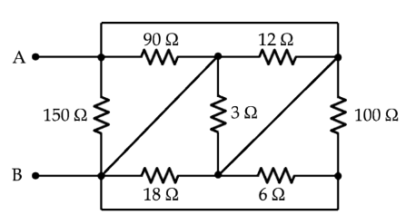
How do I determine the equivalent resistance of the circuit looking into terminals A and B? I am quite stuck and the only thing I've figured out is that there are 3 pairs of parallel resistors: 90&12, 18&6, 100&150. The diagonal wires with no resistors kind of throw me off.
-
\$\begingroup\$ We don't hand out homework solutions here. We need you to show us that you have done a substantial amount of work yourself, show us everything that you have done, then ask a specific question. Why don't you start by labeling all of the nodes in the schematic? \$\endgroup\$– Elliot AldersonCommented Mar 22, 2021 at 18:40
-
\$\begingroup\$ There was a very similar question here couple of days ago, just the diagonal lines were arranged differently. Was it your question? Can't you apply the similar technique to it? \$\endgroup\$– Eugene Sh.Commented Mar 22, 2021 at 18:42
-
\$\begingroup\$ Yes but where are you stuck and why do the diagonals throw you off? Redraw the circuit without diagonals then. \$\endgroup\$– JustmeCommented Mar 22, 2021 at 18:45
-
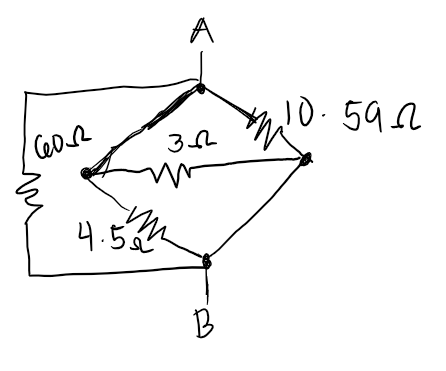
\$\begingroup\$ I've added a photo to my post to show my attempt at simplifying the circuit. I tried to research how to do it and I found a similar circuit with no empty wires and I tried to pattern it out of that. I just don't know where to go from there. Maybe you could point me in a direction. \$\endgroup\$– HolyyyCommented Mar 22, 2021 at 18:50
-
\$\begingroup\$ @EugeneSh. It wasn't my question and I'm new to the platform, could you maybe share the link to it. Thank you \$\endgroup\$– HolyyyCommented Mar 22, 2021 at 18:52
3 Answers
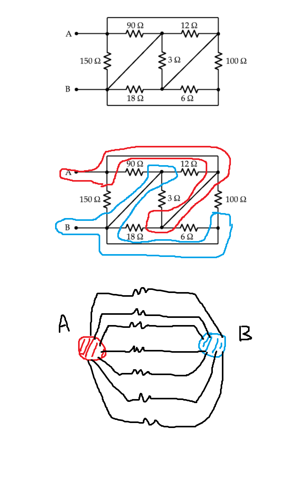
I am giving the image only. The members may frown. Only 2 nodes are there.

Redraw the circuit.
Start by putting the node labels "A" & "B" on all nodes that connect directly to the input terminals.
Then draw the circuit with all of the resistors parallel to each other where possible. Obviously, have all of the node "A" ends of the resistors at the top (or bottom) and all of the node "B" ends of the resistors at the opposite end.
The solution should be fairly obvious when you have done this.
Diagonal lines means the circuit becomes short. To the right of the circuit branch current will not flow due to circuit been short. Only on left to the short circuit current will flow. Circuit becomes now easy to solve.


