Although L298Ns are very inefficient, they're very cheap. I have two motors that require 4A+ current at load combined. Can I connect multiple L298Ns in parallel in this way to increase the overall current output? Am I going to run into any problems? 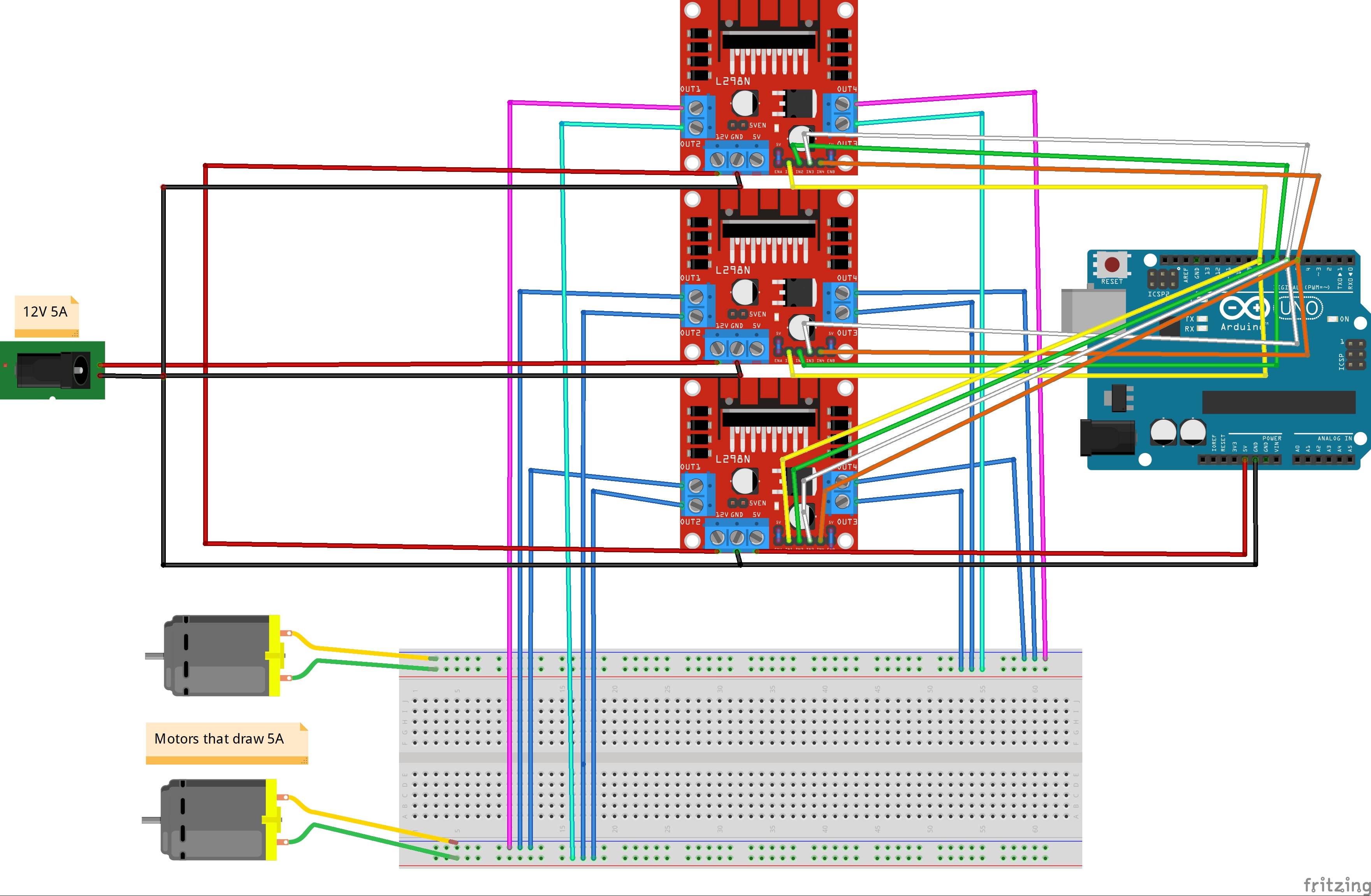
-
2\$\begingroup\$ How can you guarantee they will share the load current equally? (Hint - you can't). \$\endgroup\$– Andy akaCommented Mar 27, 2021 at 14:47
-
5\$\begingroup\$ Tip: the illustration you have posted is referred to here as a "cartoon" or wiring diagram. A schematic diagram reveals the schema or purpose of the circuit with part numbers and pin designations and is the "language" of circuits. Meanwhile your diagram shows us that you have a breadboard, two motors, an Arduino, a red PCB and a green thing. Most of the cartoon generators have schematic export functions although you will need to spend some time laying out the components sensibly and untangling the mess of wires they generate. \$\endgroup\$– TransistorCommented Mar 27, 2021 at 14:52
-
2\$\begingroup\$ you should probably not be running the current for motors through breadboard traces. \$\endgroup\$– HearthCommented Mar 27, 2021 at 14:53
-
1\$\begingroup\$ You could probably bolt them to a common heatsink (so as they heat due to their horrible performance they more-or-less heat together) and get a slight (maybe 30-50%) improvement in output current, but they are really horrible parts. Did I mention they are horrible? \$\endgroup\$– Spehro 'speff' PefhanyCommented Mar 27, 2021 at 14:55
-
2\$\begingroup\$ this sounds like a very bad idea: instead of parallelling three 1970s, very inefficient (since high-loss) motor controllers, why not simply spend a fraction of the money on something modern? If L298N is the answer, then the question started with "Let's book time travel to the year 1978..." \$\endgroup\$– Marcus MüllerCommented Mar 27, 2021 at 15:03
2 Answers
I am not endorsing wiring the L298Ns in parallel, but simply discussing the issues involved, and how it might be accomplished. As others have pointed out, an easier solution is to purchase a more robust driver.
Simply wiring the L298Ns in parallel will cause problems. A partial schematic of one of the motors, and one of the drivers, driven in one direction looks like this:
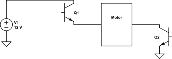
simulate this circuit – Schematic created using CircuitLab
With multiple drivers connected in parallel, a partial circuit would look like this:

A big problem with this arrangement is that the currents through the transistors may be unbalanced. Suppose Q2A is slightly warmer than Q2B or Q2C. It is likely to conduct more than 1/3 of the current. Conducting more current means that it will get hotter than Q2B and Q2C. Which will cause it conduct more of the current, etc.
If you are willing to trade some motor speed (voltage) for torque (current), you can balance the transistors to some extent by adding small value resistors between the transistors and the tie-points to the motor, like so:
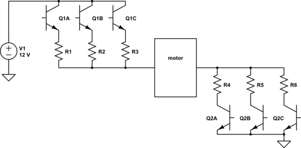
The larger the resistors, the more voltage you will lose, and hence the lower the maximum rpm of your motor. However, the larger the resistor, the greater the current balance you can achieve. Sufficient balance, and you can safely connect multiple drivers to drive your motor, thus increasing your torque. However, this only works to a point. Obviously too large a value for the resistors, and you will lose more power in the resistors than you gain by having extra transistors.
You say that the two motors will require 4A combined. You don't say whether the motors will ever require more than 2A individually. (It could be that only one motor operates at a time, and when it does it requires 4A). I will assume that you only need 2A. (BTW the L298 is advertised as capable of 4A total (for 2 drivers), so if the modules actually behaved as advertised, you could get the 4A out of a single module, but that is another story).
Assuming each transistor needs to conduct, say 0.7A, and you want, say 0.3V across each resistor, the resistor values should be 0.3/0.7 = 427m\$\Omega\$ or something in that vicinity. Although they should only dissipate 210mW, I would use 1/2 watt rated resistors. The resistors need to be matched. Tight tolerance 0.5\$\Omega\$, 0.5W resistors are commercially available.
That takes care of the issue of transistor balancing.
There is another issue that must be addressed. Shoot-through. If both transistors in a half-bridge are on simultaneously, shoot-through will occur. A large current will flow through the transistors without encountering the impedance of the motor. This is bad, so you want to ensure that shoot-through doesn't occur. By connecting the modules in parallel, you increase the possibility that a high side transistor in some module is on, while a low side transistor on the same side of the motor, but perhaps in a different module, is also on. It is important when changing voltage directions, that there is sufficient "dead-time", so that all of the transistors are off, before any new transistor is turned on. It is your responsibility to ensure that.
Once again, I am only explaining how wiring the modules in parallel might be accomplished, but I am not endorsing this as a solution to the higher level problem of how to drive the motors.
Question
Anything wrong with connecting L298Ns in parallel?
Update 2021mar30hkt1601
Preliminary testing shows that when two full H-bradges are paralleled to drive one motor:
The motor load current is shared between the two channels as 52% : 48%
The total load current is increased by 10%. In other words overall effeciency is 90%
Conclusion: It is a good idea to parallel two bridges for a bigger current
See Part 7 below for more details.
Answer
Nothing wrong. Hobbyists do it. Engineers can also do it. It all depends on cost/benefit/risk hobbyist/engineer trade offs.
Let me explain, starting with ULN2803, then L298N.
Part 1 - ULN2803A Case
ULN2803A Darlington Transistor Arrays - TI
From datasheet - Section 3 Description
The ULN2803A device is a 50V, 500 mA Darlington transistor array. The device consists of eight NPN Darlington pairs that feature high-voltage outputs with common-cathode clamp diodes for switching inductive loads. The collector-current rating of each Darlington pair is 500 mA.
The Darlington pairs may be connected in parallel for higher current capability.
Part 2 - L298N Case
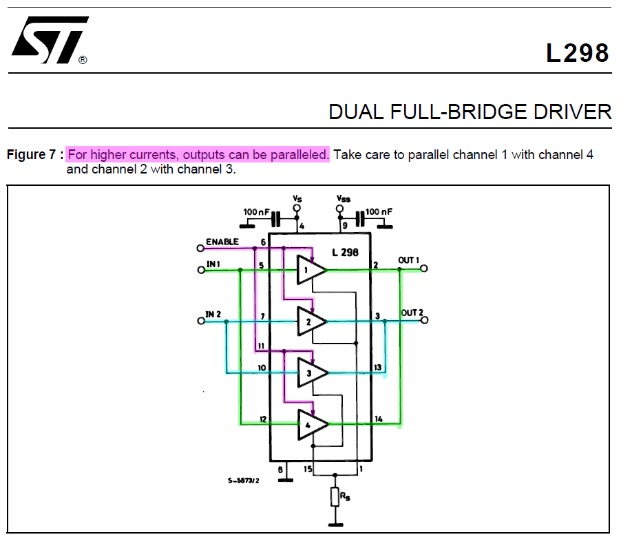
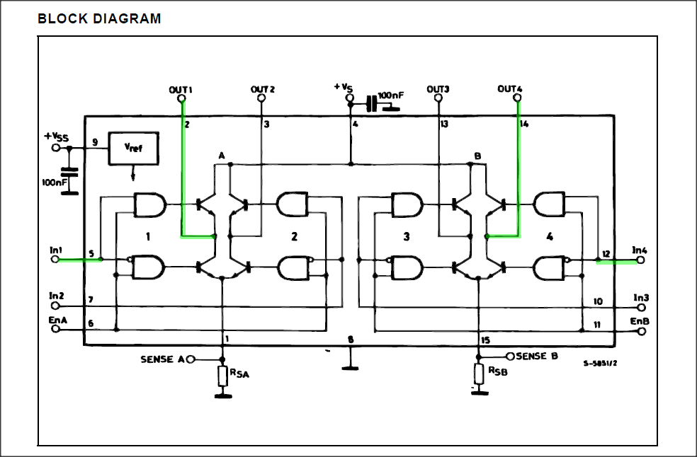
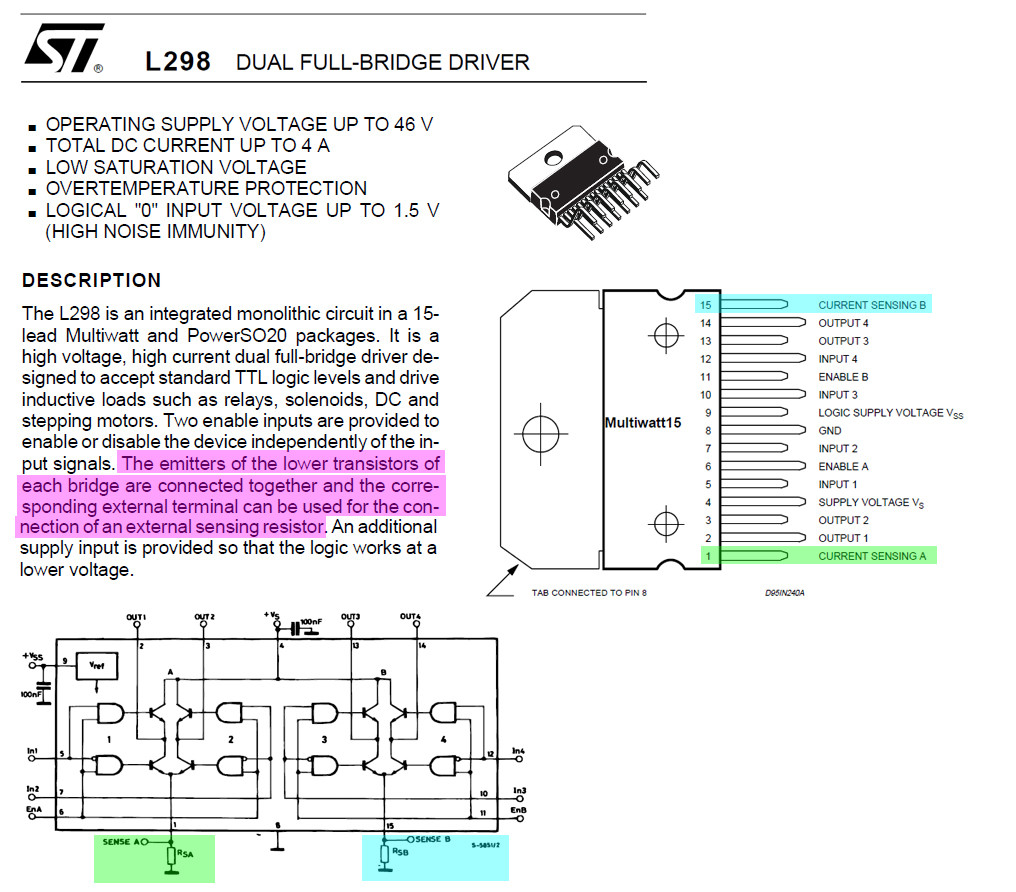
By the same ULN2803 token, L298N can also parallel output for bigger current. Since the BJTs to be paralleled are fabricated from the same die/chip, they should very nicely selfie balancing out the load current.
Part 3 - L298N Dual Full Bride DC Motor Driver Module Case
AliExpress L298N Dual Full H Bridge DC Motor Driver Module - US$1
The very popular cheapy L298N motor driver modules are for driving two 4A (update: 2A each bridge) DC motors. For a bigger motor, say 8A (update: 4A), we can parallel two drivers into one big driver.
Warning: me just friendly hobbyist. No guarantee no nothing would melt down or blow up.
Part 4 - Discussion and Recommendation
L298N output paralleling for bigger output current is a good newbie workaround. For ninjas, I would recommend forgetting the little old guy L298N, and go instead for the 40A big guy BTN7971B.
For more details on BTN7971B, see Refs 11.4, 11.5, and 11.6 of my answer to the following motor driver Q&A.
Part 5 - Proof of Concept
To prove my guess is correct, I am using a L298N module with the two channels' output paralleled, and measure the two channels's current when driving one DC motor. Below is the test procedure.
Setup a L298N module to drive two 12V DC motors, to make sure both H-Bridges are working correctly.
Remove one of the motor, and parallel both channel's outputs to drive the remaining one motor.
Use two multi-meters to measure each H-Bridge's output current, to see if they are balanced or not.
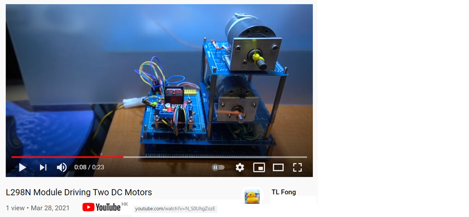
YouTube Video - L298N Module Driving Two DC Motors
Part 6 - How to measure each of the two H-bridge output current to DC motor?
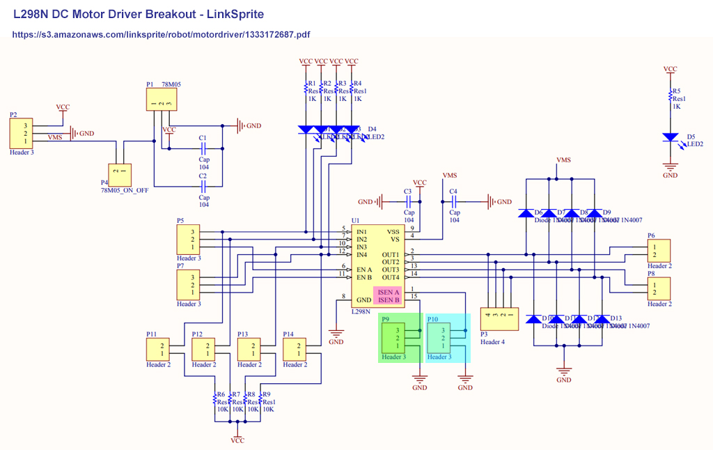
L298N has two current sense pins to measure the output current, using a current sense resistor, shown in pink/green/blue in the schematic below below (Also shown as Sense A, Rsa, and Sense B, Rsb in the last diagram of Part 2 above.).
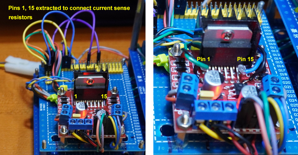
Part 7 - How to do the L298N current sensing wiring?
Most of the cheapy L298N modules do not have current sensing resistor sockets and jummpers. So we need to do some DIY wiring. Let us first look at the current sense pins to fiddle, as shown below.
Part 8 - Preliminary Test Results of two channels (full H-bridges) in parallel to drive only one motor
Step 1 - Channel 1 only
Channel 1 output to Motor 1 = 90mA
Channel 2 output Not connected = 0.7mA
Step 2 - Channel 1 and Channel 2 paralleled
Channel 1 output to Motor 1 = 52mA
Channel 2 output to Motor 1 = 48mA
Total motor current = 52mA + 48mA = 100mA
Channel 1 load = 52%
Channel 2 load current = 48%
Conclusion = nicely balanced
/ to continue, ...
-
3\$\begingroup\$ Please, please, please stop posting these blogs..! It's also not answering the question of can two or more L298Ns in parallel - you've shown a single L298N with its outputs in parallel. This is very different to two different ICs. \$\endgroup\$– awjloganCommented Mar 28, 2021 at 14:30
-
1\$\begingroup\$ Meta information like "to continue" does not belong in an answer. \$\endgroup\$ Commented Apr 8, 2021 at 10:23
-
1\$\begingroup\$ I don't mind long answers at all (we actually need comprehensive answers over terse RTFM style answers), but baby talk and fake double negatives like "me just friendly hobbyist. No guarantee no nothing" is unhelpful. \$\endgroup\$ Commented Apr 8, 2021 at 10:25
-
\$\begingroup\$ @Peter Mortensen, Well, I was once a political refugee. My use of under privileged/suppressed class/people does have a political meaning/implication, beside a little bit of healing effect. Of course I am also just a friendly hobbyist, never mind high class/elite language. \$\endgroup\$– tlfong01Commented Apr 8, 2021 at 15:09

