1
\$\begingroup\$

So basically, I want to connect a small Peltier cell to an Arduino. I know that Peltiers are very inefficient and require large amounts of power in general but I only need to create a small temperature change. Anyways, I tried connecting it directly but the amount of current I get from one pin is too little.

I was wondering what would happen if I connected, say, 5 pins as parallel connections on a breadboard. Theoretically, if each pin is giving me 40mA, I should get an output of 200mA. Is this logic correct? Furthermore, if this is true, would I have to worry about reverse current spikes damaging the Arduino?

\$\endgroup\$
3
  • \$\begingroup\$ It's probably worth mentioning the particular Arduino because it can vary depending on the AVR used. But in general apart from per-pin limits (40mA sounds a bit too high to me for most AVRs) there are normally also limits across the entire port, so in general you'd be better off using a transistor to switch it. \$\endgroup\$
    – PeterJ
    Commented May 24, 2014 at 8:19
  • \$\begingroup\$ I'm using Arduino Mega 2560 R3. What I really want to do is somehow deliver around 200mA of current to the peltier cell using a microcontroller. Is there some other way I could do this? \$\endgroup\$ Commented May 24, 2014 at 8:41
  • 1
    \$\begingroup\$ I believe for a peltier you'd probably be best to use a MOSFET and PWM but never having controlled one I'm not 100% sure on any caveats. But you'd probably be better to edit your question to say the end result you're after to narrow it down to what you really need. Trying to use the maximum drive current of the pins as a form of current limiting probably isn't a good idea. \$\endgroup\$
    – PeterJ
    Commented May 24, 2014 at 8:49

1 Answer 1

2
\$\begingroup\$

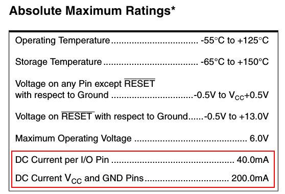
Using multiple pins in parallel will share the current but there is a max allowed current per pin and for the entire mcu, you should keep the current within specs for both.

The Atmel Mega 2560 datasheet, in section 31 (electrical characteristics), says:

enter image description here

but note that this is absolute max, so you shouldn't use that levels in normal operation. The normal operating current seems to be in the level of 20mA since that is the mentioned current in several parameters in the spec list and the graphs.

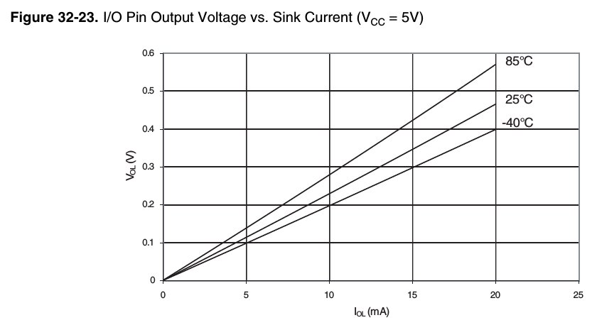
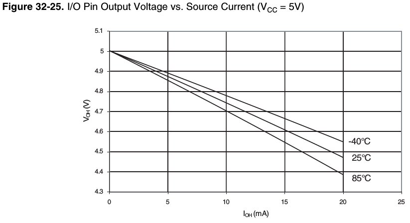
Also note that the pin voltage drops as the voltage you sink/source increases

enter image description here

enter image description here

I think you are better off using a driver for the Peltier cell, you can can use an IC, a mosfet or a transistor.

\$\endgroup\$
2
  • \$\begingroup\$ Ok, thanks for the info. Is there any particular IC you can think of that would be suitable for driving the cell? Another option I was considering was driving the cell through an independent battery-powered circuit that would be controlled by Arduino through an opto-isolated relay. do you think this would work? \$\endgroup\$ Commented May 24, 2014 at 9:33
  • \$\begingroup\$ @user3425451 I don't have any particular IC in mind. I meant the ULN series (2803, 2003 etc) IC that are used as generic drivers in several circuits but a mosfet will have a much lower voltage drop. You can use an isolated circuit with an optocoupler between the Arduino and the Peltier circuit, just make sure to limit the current of the opto-led. \$\endgroup\$
    – alexan_e
    Commented May 24, 2014 at 10:11

Your Answer

By clicking “Post Your Answer”, you agree to our terms of service and acknowledge you have read our privacy policy.

Not the answer you're looking for? Browse other questions tagged or ask your own question.