4
\$\begingroup\$

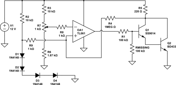
I am repairing a commercial frequency counter (brand to remain anonymous) that had the crystal oven visibly overheat. There is a small PCB in the oven that holds the crystals, the oscillator circuit, four diodes connected in series whose voltage drop changes with temperature, and a 220 ohm 1 Watt resistor whose voltage is modulated to provide the heat.

When looking at the circuit to repair it, I think I found a serious design error that explains why it overheated. See schematic below, I may have drawn the diodes on the wrong input - it doesn't matter for my point. Also, ignore the 'Rmissing' for now - that is my proposed solution, it is 'missing' from the manufacturer's design.

schematic

simulate this circuit – Schematic created using CircuitLab

I think the minimum voltage the TL061 output can reach (it is not a rail-to-rail op amp) is dangerously close to the minimum 'turn-on' voltage of the Darlington pair, meaning given tolerance overlap it is possible the op amp could never shut off the Darlington pair, leading to the heater staying on.

I simulated this in LTSpice and it confirms my suspicion. I also confirmed that adding some resistance from the base of the Darlington pair to GND, that is the 'Rmissing' 100k resistor, creates a voltage divider and pulls the base voltage comfortably into the off region of the Darlington pair when the op amp is pulling its output low, yet still allows plenty of base voltage when the op amp output is at max output voltage.

Thoughts on my theory?

(Edit #1: My apologies, I completely missed the shorted inputs. I fixed that plus added the exact input circuit and all component values.)

\$\endgroup\$
1
  • \$\begingroup\$ You’ve shorted the differential input. The circuit could be for an SC cut 10 MHz TCXO. The flat part of the elevated temperature curve of T vs f is where one can tune the error to < 1e-11 or -12. If the diodes are being used as a thermometer, it needs to be calibrated for this temperature. OTP protection does not seem to exist. \$\endgroup\$
    – D.A.S.
    Commented Mar 30, 2021 at 18:29

2 Answers 2

1
\$\begingroup\$

Seems like it could be be marginal, especially since the Vbe drops on the Darlington pair decrease as the transistors heat.

I wonder if they designed it for some other op-amp and the JFET op-amp was substituted. I don't see any need for the JFET characteristics. That sort of thing tends to happen when the original designer moves on.

\$\endgroup\$
2
  • \$\begingroup\$ What Vce(sat) do you expect with a 100k load? For Vol \$\endgroup\$
    – D.A.S.
    Commented Mar 31, 2021 at 16:46
  • \$\begingroup\$ @TonyStewartSunnyskyguyEE75 The schematic is a bit complex to just look at it. I think I see two Vbe drops which is bad news. There's effectively no load (just a few uA of base current to turn it on). \$\endgroup\$ Commented Mar 31, 2021 at 16:54
1
\$\begingroup\$

Last Update

I was correct in my 1st revue.

Although certainly marginal, I simulated here a version of the original TL061 with a Darlington NPN and the feedback network and made it work with and without your suggested change. This 1977 technology is basically laser trimmed differential N type JFETs nulled for offset slapped on a uA741 with minor changes for thermal stability.

I still suspect TI might have made some changes. We will never know for sure without a task force and date codes. (LoL) back to h/w floor sanding for me. Maybe the others can comment.

Update

After reviewing the TI Rev J datasheet, I agree that your solution is a brilliant one. I suspect some very minor changes in the differential emitter follower circuit may have caused a change in the no load Vout drop above Vee when NSC released this in 1977. It has a laser-trimmed internal bias with ultra low 2 uC/‘C Vio offset-stability BiFET Op Amp.

Much like a uA741 , driving a Darlington from a Darlington even with 100k will depend on very subtle changes. If this was made after 1977 with a TI process on the TL081 rev ? , I agree that the driver voltage is marginal. It would be a matter of if the Darlington was hotter from the oven leakage of heat more than the Op Amp thereby like the diode string thermal sensors drop -2.1 (?) mV/‘C, the differential voltage may be enough to drive Ic= 1uA thru 100k in nanoamperes.

So good on you for coming up with this production problem DIY solution.

Reducing the gain by 50% could be tolerated with minor adjustments of other resistors to balance the SC cut Xtal to within 1’C of it’s df/dT=0 curve minimum. The fixed parallel bias R’s would have been a SOT select-on-test in production to tweak within uV or <1’C error in the oven. This is partly assuming the unknown vintage of your IC, TCXO and probably HP or TEK counter. (Or was it a clone?)

——-

Bob Widlar in 1967 published an article on the interesting accurate properties Vbe verses temperature.

It took decades later before they became disposable thermometers in hospitals.

I recognize this as a class SC cut TCXO usually in 10MHz in double insulated ovens from Vectron for HP vintage precision counters that sold for about $350 for 1e-11 stability per year. They only needed to have a precise oven temperature where the df/dT=0 so that outside thermal variations attenuated by the insulation would cause zero frequency error.

I see no problems in this design, but a few mistakes/omissions in your schematic.

  • Base Current is limited by design with 100k into a Darlington (hFE=10k) to protect it.

  • The 2W 220 resistor will have a maximum of ~ 600 mW if anything in the regulator fails.

  • the Vin+ is now the negative feedback input with the Darlington’s inverted collector output.

  • the Vin- port may be biased near >= 1.5V where the 4x diode string are high Z near 1uA to avoid self heating. Yet still give high gain error feedback with 1M with a 1 degree C or so tolerance on the setpoint control.

  • The Vin- port is pulled up perhaps with a similar high impedance to prebias the diodes and then the larger 1M negative feedback is balances the diode current-voltage level for the desired setpoint.

Conclusion

Without values, I see no problems with the design other than your shorting the Op Amp inputs. Reducing the gain with a Vbe pull down is just another way of reducing the gain that is set by all the other resistors. So something has shifted. (Failed in setpoint or pullup resistor values)
\$\endgroup\$
2
  • \$\begingroup\$ I see how the gain is set by the input and feedback resistors, but my concern is how close to GND can the TL061 output get? The datasheet lists the typical +15V Vcc+ and -15V Vcc- performance which is +/-10V min and +/-13.5V typical. Scaling that to +12V Vcc+ and 0V Vcc- I get min of +10 and +2V and typical would be +11.4V and +0.6V. A base voltage above about 1.2V will turn on the Darlington pair - hence my concern if the TL061 had 'typical' performance there isn't enough voltage drop across that 100k resistor with 2.0V on the op amp output to ever shut off the heater. \$\endgroup\$ Commented Mar 31, 2021 at 14:59
  • \$\begingroup\$ Since the output current is limited by 100k the drop will be less than typical. 1mA to 10mA?? I didn’t use the datasheet as I know the Rce is <<<1% of 100k \$\endgroup\$
    – D.A.S.
    Commented Mar 31, 2021 at 16:44

Your Answer

By clicking “Post Your Answer”, you agree to our terms of service and acknowledge you have read our privacy policy.

Not the answer you're looking for? Browse other questions tagged or ask your own question.