0
\$\begingroup\$

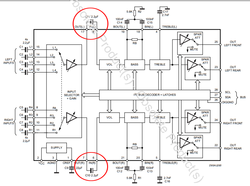
Fiddling around with my TDA7318 mixer chip, I've found a strange contradiction between the suggested "test circuit" cited in the manufacturer's datasheet, and the schematic published by someone who made up a complete audio solution by using this chip. It's all about two connections, both directly between two neigboring pins:

  • Pin #6 (IN (R)) and #7 (OUT (R))
  • Pin #16 (IN (L)) and #17 (OUT (L))

The manufacturer suggests the use of one 2.2 µF capacitor on each connection, whereas the abovementioned maker simply laid direct connections (just a couple of millimeters of wire) between the respective pins.

Which alternative is better? I've been thinking of coupling capacitors here, but which purpose should they serve when cross-connecting two pins on the same chip?

\$\endgroup\$

2 Answers 2

2
\$\begingroup\$

There is not much in the datasheet to work with, however, it is clear that the capacitor removes a DC path between two different internal modules of the chip.

Any DC bias that might get added on the input selector + gain block would pass on to the volume block, unless the capacitor is there to remove it so the volume block can set its own internal input bias voltage.

Since the manufacturer suggests this configuration, it would be more preferable than to do it against manufacturer suggestions, especially since the datasheet does not describe the internal operation in a detailed way to let the designer choose between the two options.

\$\endgroup\$
1
\$\begingroup\$

Next time, include a picture from the datasheet to make it easier to show what you mean:

enter image description here

These capacitors are needed called "AC coupling capacitors". What they do is block the DC voltage coming out of the input selector block on the left, but let the AC (audio signal) pass into the next stage called vol which is for volume control.

If the DC signal was not blocked then the DC output voltage of the input stage would disrupt the behavior of the next stage, the chip simply might not work properly.

There are more AC coupling capacitors at the inputs, C1 to C8 are all AC coupling capacitors.

These capacitors need to be large enough to properly pass the audio signal. That means they need to have a value that is too large to integrate on a chip. On a chip a 100 pF capacitor is already quite large. Note how these capacitors are all 2.2 uF, way too large to integrate on the chip. So they have to be outside the chip as a discrete component.

A designer that goes against the manufacturer's recommendation of including these two capacitors is taking a risk. The chip might not perform in an optimal way. If the capacitors were not really needed then that would be reflected in the datasheet as leaving out capacitors save cost and that is what all customers want.

\$\endgroup\$
3
  • \$\begingroup\$ Would this mean that the "Input Selector + Gain" stage does add some DC component to the audio signal, which then has to be filtered out by using the coupling caps? \$\endgroup\$
    – Neppomuk
    Commented Apr 2, 2021 at 21:24
  • 1
    \$\begingroup\$ @Neppomuk Yes, this IC appears to be able to work on a single supply, then all signals need to have a DC bias (usually half the supply voltage) as it is impossible to have negative voltages, as there is no supply for that. Only circuits that use a positive and a negative supply (for example: +15 V and -15V) can the circuits be made such that the DC bias = 0 V so no DC voltage. \$\endgroup\$ Commented Apr 3, 2021 at 12:01
  • \$\begingroup\$ OK, so I've gotta fish the DC part out of the signal in any case. And yeah, the TDA7318 is supplied with +9V only. \$\endgroup\$
    – Neppomuk
    Commented Apr 3, 2021 at 20:41

Your Answer

By clicking “Post Your Answer”, you agree to our terms of service and acknowledge you have read our privacy policy.

Not the answer you're looking for? Browse other questions tagged or ask your own question.