0
\$\begingroup\$

I have a circuit with IGBTs which charges and discharges two different capacitor lines as a function of the voltage. i.e. when a voltage is detected below 160V, Q1 charges C1 and when a voltage over 160V and below 500V is detected, Q2 charges C2, and all voltages over 500V and up to 1000V are charged with Q3 and C2 and C3 in series.

After charging, the capacitors are discharged by R1 and R3 depending on which circuit was used.

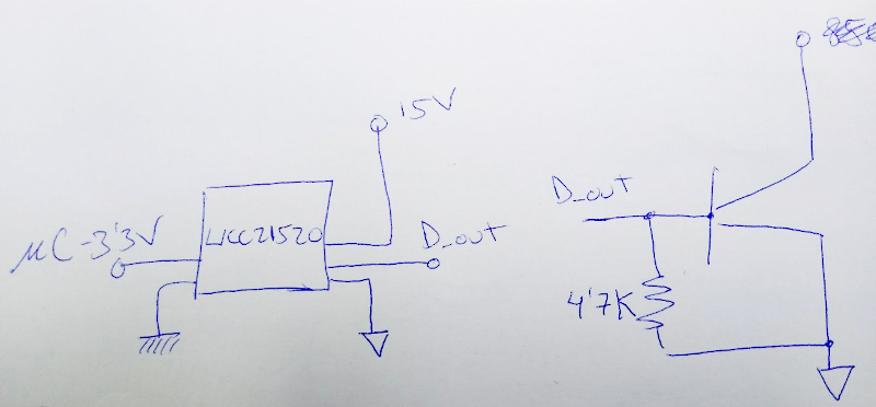
All IGBTs are driven with a UCC21520 driver by means of a microcontroller. Isolated power supplies are obtained from an NMK1515SC DCDC converter with 3000Vrms isolation during 1 second.
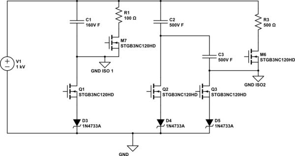
schematic

simulate this circuit – Schematic created using CircuitLab

The problem is that charging at high voltages (over 800V typically,) Q1 is failing, going into short-circuit and therefore C1 gets exposed to 800V and ends up exploding.

Sometimes it also happens in Q2, although less frequently. I suspect various things could be happening but not 100% in any of them and not even sure if it could be some other thing:

  • When Q3 is closed V_CE of Q1 changes from 850 to 0V and then slowly back to 850V with the charging of C2 and C3. This without Q1 beign activated and could be the cause of the failue of Q1.
  • Right now not using a resistor betwenn the IGBT driver and the IGBT gate which could cause voltage overshoot and cause the IGBT to fail. But this should occur on the IGBT beign triggered and not another one.
  • Maybe IGBT model is not the most appropiate.

Any other ideas would be very much appreciated.

IGBT datasheet.

IGBT driver circuit:

enter image description here

\$\endgroup\$
3
  • \$\begingroup\$ Data sheet links for the IGBTs are needed. \$\endgroup\$
    – Andy aka
    Commented Apr 5, 2021 at 16:59
  • \$\begingroup\$ Datasheet added \$\endgroup\$
    – SolarTec
    Commented Apr 5, 2021 at 17:38
  • \$\begingroup\$ Looking at this and your problem. with the lack of inrush current protect on the zener diodes. Those are the little 1/2 amp glass type, that most of the time go open before shorting. \$\endgroup\$ Commented Apr 17, 2021 at 15:56

2 Answers 2

2
\$\begingroup\$

enter image description here

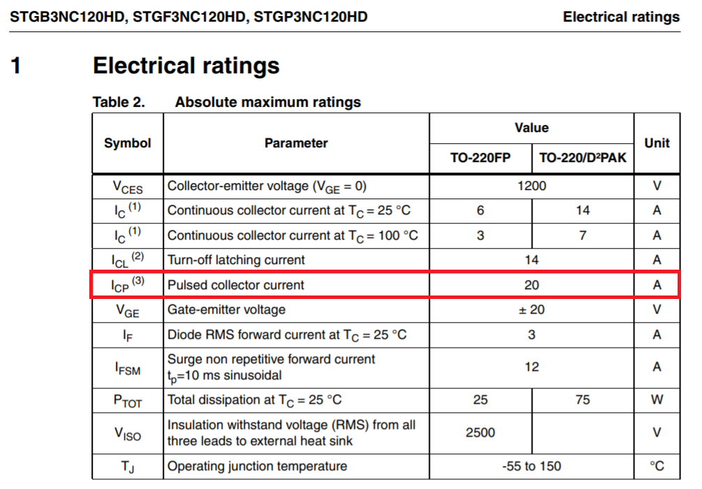
Without some form of current limiting external to the IGBT, turning it on when there are hundreds of volts on the supply is going to generate a pulse of current due to the physical nature of a discharged capacitor. That current can only be limited by the supply itself and the ESR of the capacitor. The IGBT data sheet says this: -

enter image description here

So, if the pulse of current exceeds 20 amps, you could be in trouble. The IGBT you have used is extremely fast at turning on with a current rise time of typically 3.5 ns and that, to me, suggests it is a candidate to consider.

\$\endgroup\$
8
  • \$\begingroup\$ The source itself is limited to less than 20A although because of the nature of it (solar panel) it could emit a larger current pulse due to its internal capacitance. However, not sure if that explains the other IGBT failing and not the one that is being turned on. Do you think? \$\endgroup\$
    – SolarTec
    Commented Apr 5, 2021 at 17:40
  • \$\begingroup\$ Do you suggest trying with an IGBT with a slower turning on time? We just came back from testing a new IGBT and it has not failed. Although testing has been done at very low current (1.5A) We will do more testing tomorrow at higher currents (littelfuse.com/~/media/electronics/datasheets/discrete_igbts/… ) \$\endgroup\$
    – SolarTec
    Commented Apr 5, 2021 at 17:45
  • 3
    \$\begingroup\$ I'm not particularly suggesting you do anything other than try and figure out what the peak current might be. Try using a high speed current probe method. \$\endgroup\$
    – Andy aka
    Commented Apr 5, 2021 at 18:06
  • \$\begingroup\$ Tried again today with the new IGBT rated at 40Amps and at the moment of connecting V1 (400V), Q1 started conducting inmediately without driving any of the IGBTs. We tested the pins and had a short circuit between Gate and Emitter. We disconnected, connected again and again it started conducting automatically. Tested pins again and now we had a short also between Collector and Emitter. Really don't know what could be happening. Also dont' know why only Q1 is failing but not Q2 \$\endgroup\$
    – SolarTec
    Commented Apr 6, 2021 at 14:47
  • \$\begingroup\$ Well, that may be something else or the same thing so, what you might have to do is reveal more of your circuit and more of the details of the solar panel and panel to circuit board interface wiring plus any earths you might have on the system. Pretty much most of your schematic might be needed but, this question is probably done now that we have established that the original IGBT has a maximum current rating that is a tad low. \$\endgroup\$
    – Andy aka
    Commented Apr 6, 2021 at 15:22
0
\$\begingroup\$

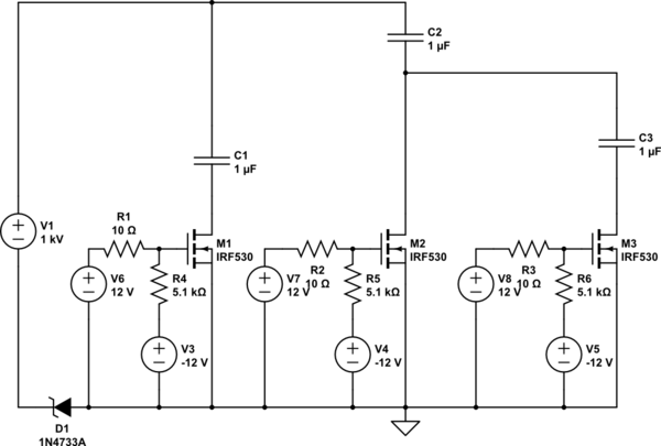
Problem seemed to be the accidental turn on off Q1 possibly due to Miller current. In order to avoid it we have connected the pull-down resistor to -12V so as to have a negative VGE during turn off. New schematic is shown where V6, V7 and V8 represent the drivers voltage when turned on. When turned off the driver outputs -12V and prevents IGBT accidental turn on due to induced voltages at the gate. 10Ohm gate resistors where also added to slow down IGBT turn on and avoid overvoltage events during turn on and turn off

schematic

simulate this circuit – Schematic created using CircuitLab

\$\endgroup\$

Your Answer

By clicking “Post Your Answer”, you agree to our terms of service and acknowledge you have read our privacy policy.

Not the answer you're looking for? Browse other questions tagged or ask your own question.