1
\$\begingroup\$

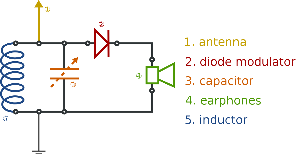
This figure is a crystal radio reciever and there is no active element involved in it.

LC filter is passive. Then how one can know that what output voltage LC circuit is offering to the diode and earphones?

Can the output voltage from LC circuit be found by using a multimeter/voltmeter or there is any other way to find the output voltage from LC circuit?

enter image description here

\$\endgroup\$
7
  • \$\begingroup\$ Where is the crystal? \$\endgroup\$ Commented May 3, 2021 at 6:30
  • 2
    \$\begingroup\$ @Marko, A "Crystal" detector is the old (really old) name for a diode (when it was actually made from a crystal chunk of Galena). So a radio design made from this type of component was called a Crystal Radio. \$\endgroup\$
    – Nedd
    Commented May 3, 2021 at 6:43
  • 1
    \$\begingroup\$ Can the output voltage from LC circuit be found by using a multimeter/voltmeter or there is any other way to find the output voltage from LC circuit? - use an oscilloscope. \$\endgroup\$
    – Andy aka
    Commented May 3, 2021 at 7:35
  • 1
    \$\begingroup\$ That's precisely what o-scopes do best. \$\endgroup\$
    – Andy aka
    Commented May 3, 2021 at 14:37
  • 1
    \$\begingroup\$ The "crystal" was the cat's whisker galena detector, but (unrelated) the typical earpiece was also called a "crystal" earpiece. Today we'd probably call it a piezoelectric earpiece. \$\endgroup\$ Commented May 3, 2021 at 15:31

2 Answers 2

1
\$\begingroup\$

This discussion assumes the circuit is used to receive medium-frequency AM broadcast band.


Since there are no active elements in this circuit, the only RF power available comes from the antenna, and possibly from the earth connection wire too.
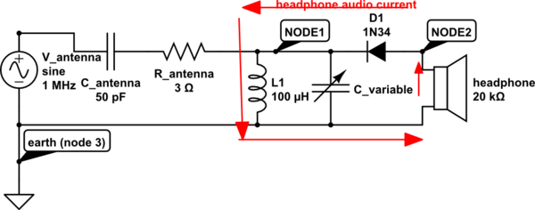
Very little power is available: matching impedances with inductance and/or capacitance is essential to delivering audible power to headphones. The diode is the element that generates audio power from the available RF power. Causing a good deal of headphone audio current to flow is the goal.

Measuring voltages at either of the two nodes in this circuit (with respect to the third node earth, which is assumed as zero volts) requires knowledge of the circuit impedance at that node.
The diode efficiency at converting RF to audio is helped by having a high RF voltage at the antenna node. This is helped by the tuned LC resonator, which maximizes its impedance at one particular RF frequency. The antenna is often shown as a simple wire, but it usually adds a capacitive reactance, and small series resistance to this resonator.
schematic

simulate this circuit – Schematic created using CircuitLab

In this simple circuit, power transfer is aided by keeping impedances at NODE1 and at NODE2 high. High-impedance headphones are rare today, but more common decades ago. Low impedance headphones (or speaker) generally give poor results because impedance-matching is not optimal.
Note that both audio current and RF current flow through L1.

TLDR:
We usually assume that NODE3 is always at zero volts for both RF and audio. Many folks omit this connection, and get disappointing results due to the whole circuit floating...little RF power is delivered to the LC resonator. NODE3 must be grounded in an effort to produce RF currents in the LC resonator.

Measuring voltages at NODE1 or NODE2 with a grounded oscilloscope might yield respectable voltages, but when the oscilloscope is disconnected, less audio is heard (because the ground is now missing).

Measuring audio voltages from NODE2 to NODE3 with a multimeter might give some indication provided a good earth ground is connected to NODE3 (very few multimeters include their own ground connection). A digital multimeter often gives about three readings-per-second, and these numbers might jump about randomly, indicating audio voltage or current.

\$\endgroup\$
5
  • \$\begingroup\$ Can this circuit diagram with these values be made on a bread board? Will it work on breadboard? That was really a very nice answer. Thanks alot. \$\endgroup\$
    – Alex
    Commented May 5, 2021 at 7:36
  • 1
    \$\begingroup\$ For the AM broadcast band, a breadboard is fine. The inductor value is a problem, because the value you choose depends on the antenna electrical characteristics. The antenna adds capacitance - when combined with the variable capacitor on your breadboard, and the inductor, resonant frequency can change. Headphone impedance should be high - I've used 4000-ohm headphones, and 2000-ohm headphones with only a diode in parallel successfully (loud audio). More common 32-ohm headphones or 8-ohm speaker give poor results. \$\endgroup\$
    – glen_geek
    Commented May 5, 2021 at 16:24
  • \$\begingroup\$ "The antenna adds capacitance - when combined with the variable capacitor on your breadboard, and the inductor, resonant frequency can change." Can this problem be fixed? \$\endgroup\$
    – Alex
    Commented May 5, 2021 at 19:39
  • 1
    \$\begingroup\$ Alex, unless your antenna wire is really long, it will add capacitance, and it will provide more signal power too. If you really want good signal strength, impedance-match your antenna to the LC resonator on your breadboard. Matching impedance isn't easy, because both your antenna's impedance, and ground impedance are unknown....it is an advanced project taken on by dedicated enthusiasts. Impedance matching delivers power as efficiently as possible into the resonator - no power is lost in the capacitive component of the antenna, just transferred along the circuit. \$\endgroup\$
    – glen_geek
    Commented May 5, 2021 at 20:38
  • \$\begingroup\$ Again Thanks alot @glen_geek. Please do not die of Corona or anything else. It seems that world has to learn alot from you. \$\endgroup\$
    – Alex
    Commented May 5, 2021 at 21:13
2
\$\begingroup\$

The LC circuit exists to select the AM station in this corcuit here. These devices are intended to be connected to an antenna large enough to pick up significant AM signal (there is no amplification, the only power source is the received signal itself). Also the earpiece should be very high impedance in order to efficiently convert the tiny signal into sound.

You can't really know from the diagram what the voltage out is. It's just a filtered (frequency selected) version of the signal picked up on the antenna. Without it, you should hear wideband noise, with any transmitted signals probably lost in the noise.

The voltage across the speaker is just the voltage available on the (loaded) antenna (which depends on received signal strength and the antenna itself), half-rectified, filtered according to the characteristics of the tank circuit, and less a diode drop.

\$\endgroup\$
3
  • \$\begingroup\$ Yes you are right. So how can we get the amplitude of the AM signal? @danmcb \$\endgroup\$
    – Alex
    Commented May 3, 2021 at 14:34
  • \$\begingroup\$ And that amplitude of the signal is also the amplitude of the voltage from the LC circuit to the source. Am I right? \$\endgroup\$
    – Alex
    Commented May 3, 2021 at 14:39
  • 1
    \$\begingroup\$ it's whatever is picked up on the (loaded) antenna, but half-rectified and less a diode drop. Actually that should have been in my answer - I'll add it. \$\endgroup\$
    – danmcb
    Commented May 3, 2021 at 14:40

Your Answer

By clicking “Post Your Answer”, you agree to our terms of service and acknowledge you have read our privacy policy.

Not the answer you're looking for? Browse other questions tagged or ask your own question.