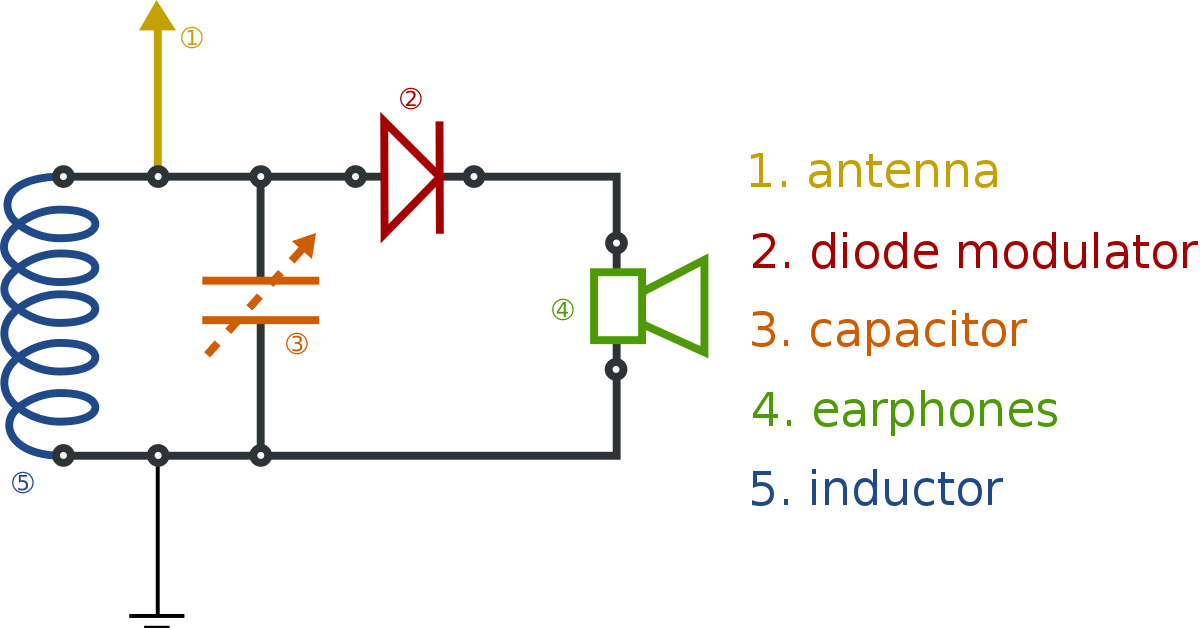
Is it possible to design this circuit of crystal radio reciever on
bread board?
Assuming that you have designed it correctly and assuming you are interested in radio frequencies that are sub 10 MHz, then it can certainly be implemented on a breadboard. But, to design it you need to have: -
- An antenna that is around one-tenth of one-quarter of the wavelength of the carrier wave.
- A germanium detector diode because it has a low forward volt-drop and therefore makes it easier to amplitude demodulate weaker local radio transmissions.
- High impedance earphones so that the energy taken from the tuned circuit does not damp it too much and cause loss of channel selectivity.
After tuning the LC tank circuit to the required frequency.....
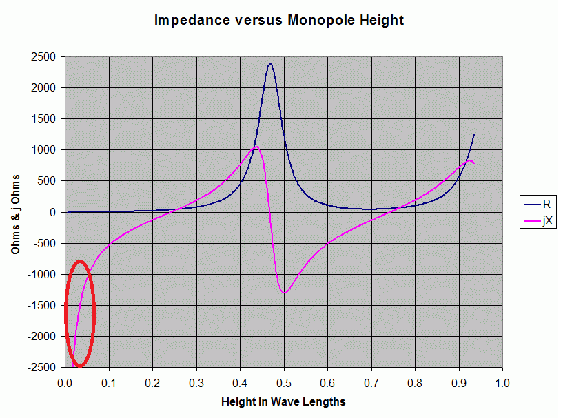
It is the antenna's self-capacitance and the tuning capacitor together that form the tuned circuit with the inductor - I'm mentioning this because when using a "short" antenna (as per my note above about the length being one-tenth of one-quarter), the antenna acts as a capacitive source and allows quite selective tuning. Making an antenna that is quarter wave matched will not work effectively at all with this circuit. Yes you might get more signal, but the tuning capability will be very poor and you'll hear several broadcast stations simultaneously (not a desirable effect). It's all down to the projected antenna impedance and an effective crystal radio does require an electrically short antenna.

The picture above comes from this Q and A. I've drawn a red area that represents the monopole length being between one-tenth and one-fifth of a standard quarter wavelength. This is the optimal length of the crystal radio antenna. In other words it should project a capacitive impedance of around 1000 to 2000 ohms. At 1 MHz, that would be around 100 pF.
Also note that the resistive element of the antenna is now a fraction of what it is at standard quarter wave frequencies and this does indeed boost channel selectivity by significantly increasing tuned circuit Q factor. The counter-side to this is that the received signal power is significantly smaller when the antenna is "short" but, as with most simple circuit implementations you can't simultaneously eat your cake and have it.
Given that a breadboard might introduce an extra 5 or 10 pF per node, you can see that it won't be a big deal.


