0
\$\begingroup\$

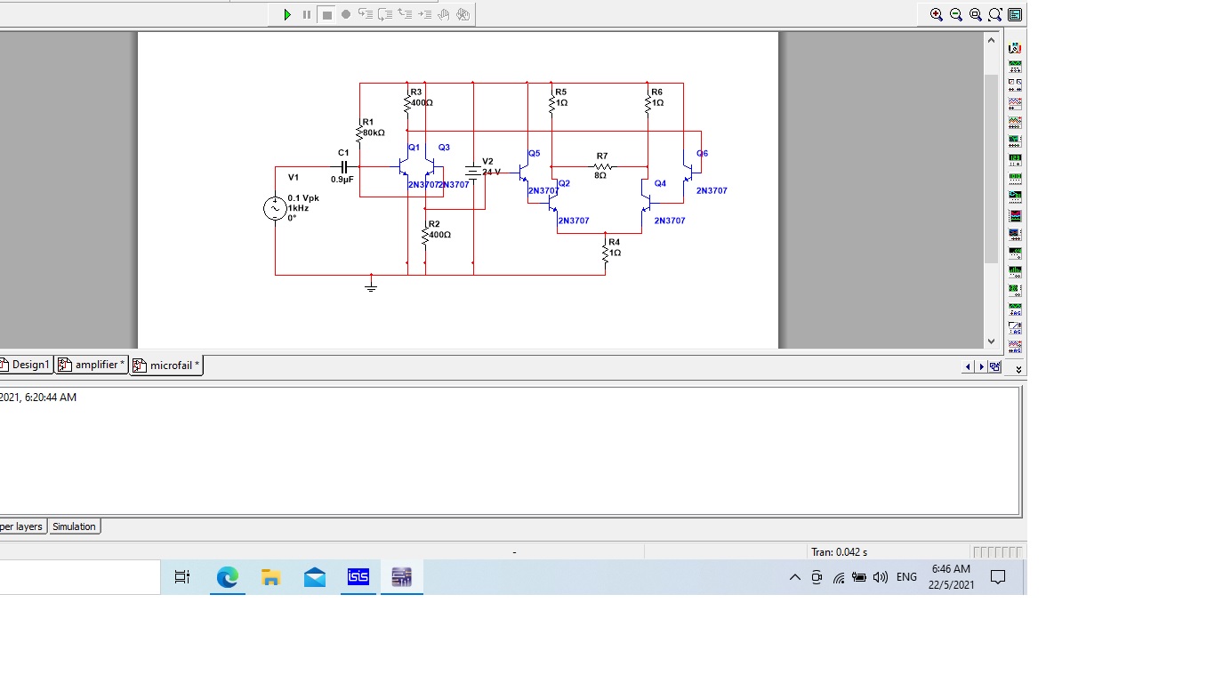
I am trying to construct an audio amplifier circuit as below(which is not working). Is there any modification can be done in order for it to work?

From my understanding, the signal from the input V1/microphone will be amplified at the collector of Q1 and same signal will be amplified at emitter Q3 as well but in opposite polarity(correct me if I'm wrong). This signal is then sent to differential amplifier circuit to get twice the amplified input signal by using a pair of Darlington construction that can then get further amplify by a gain but it is not working? enter image description here
\$\endgroup\$
2
  • 1
    \$\begingroup\$ Normally, I'd just recommend that you look at the LM380 or LM386 schematics (widely available) and learn from them. But given what I see in your design, I'm imagining that you don't want to learn from them, but instead want to come up with a different approach of your own. If so, then I think you need to spend some time explaining, in detail, how you approached the design and how you arrived at the values and topology. Be detailed, please. Or, have a look at the LM380/LM386 and see if you can learn from their approach. \$\endgroup\$
    – jonk
    Commented May 21, 2021 at 23:13
  • 1
    \$\begingroup\$ Please crop your images, for the benefit of readers with small screens. \$\endgroup\$ Commented May 22, 2021 at 0:10

2 Answers 2

1
\$\begingroup\$

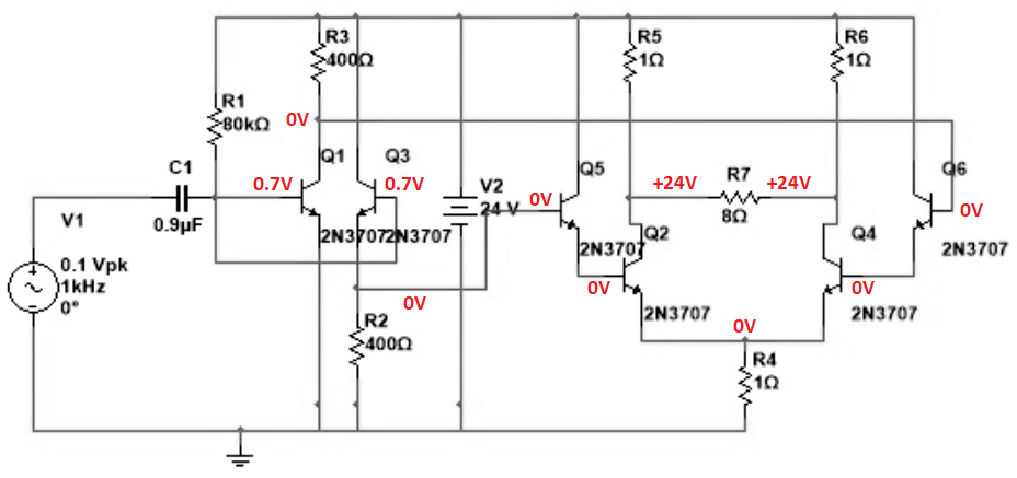
Your input transistors are not biased properly. Most of your resistor values are much too low. Audio amplifiers are usually class-AB or class-D push-pull but yours is class-A that produces so much heat that your little old transistors would melt quickly if the biasing was correct. Here are its DC idle voltages: amplifier

\$\endgroup\$
0
1
\$\begingroup\$

Replace the input stage/phase splitter with a proper differential amplifier, or separate voltage amp and phase splitter stages.. Currently the two phases have very different voltage gains, in addition to the biassing problems.

Otherwise (given suitable output transistors and heatsinks, rated for continuous 12A, peak 24A each) it should "work" for a suitable definition of "work" which includes wasting somewhere around half a kilowatt. I'd recommend running it off 12V rather than 24V until you get the bugs out.

\$\endgroup\$
1
  • \$\begingroup\$ I see, this circuit identified as "phase splitter", I came across this circuit before but without knowing the keyword is not possible for me to search for relevant circuit. Thank you. \$\endgroup\$
    – chuackt
    Commented May 22, 2021 at 18:28

Your Answer

By clicking “Post Your Answer”, you agree to our terms of service and acknowledge you have read our privacy policy.

Not the answer you're looking for? Browse other questions tagged or ask your own question.