1
\$\begingroup\$

I'm trying to do an ngspice simulation of a 1KHz astable multi-vibrator.

While I can achieve oscillations the output is very erratic and all over the place. [edit: two good responses below who said what I'm seeing is noise and not oscillations -- thank you]. I'm providing the schematic here: enter image description here
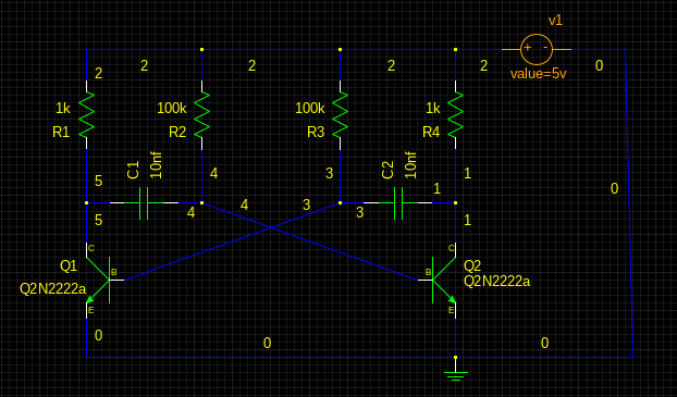
Can anyone help point me in the right direction?

I'm attaching the netlist and model file for the transistors.

* gnetlist -g spice-sdb -o netlists/multivibrator.net schematics/multivibrator.sch
*********************************************************
* Spice file generated by gnetlist                      *
* spice-sdb version 4.28.2007 by SDB --                 *
* provides advanced spice netlisting capability.        *
* Documentation at http://www.brorson.com/gEDA/SPICE/   *
*********************************************************
*vvvvvvvv  Included SPICE model from ./models/2N2222.mod vvvvvvvv
**************************************
*      Model Generated by MODPEX     *
*Copyright(c) Symmetry Design Systems*
*         All Rights Reserved        *
*    UNPUBLISHED LICENSED SOFTWARE   *
*   Contains Proprietary Information *
*      Which is The Property of      *
*     SYMMETRY OR ITS LICENSORS      *
*Commercial Use or Resale Restricted *
*   by Symmetry License Agreement    *
**************************************
* Model generated on Feb 28, 13
* MODEL FORMAT: PSpice
.MODEL Q2n2222a npn
+IS=3.88184e-14 BF=929.846 NF=1.10496 VAF=16.5003
+IKF=0.019539 ISE=1.0168e-11 NE=1.94752 BR=48.4545
+NR=1.07004 VAR=40.538 IKR=0.19539 ISC=1.0168e-11
+NC=4 RB=0.1 IRB=0.1 RBM=0.1
+RE=0.0001 RC=0.426673 XTB=0.1 XTI=1
+EG=1.05 CJE=2.23677e-11 VJE=0.582701 MJE=0.63466
+TF=4.06711e-10 XTF=3.92912 VTF=17712.6 ITF=0.4334
+CJC=2.23943e-11 VJC=0.576146 MJC=0.632796 XCJC=1
+FC=0.170253 CJS=0 VJS=0.75 MJS=0.5
+TR=1e-07 PTF=0 KF=0 AF=1

*^^^^^^^^  End of included SPICE model from ./models/2N2222.mod ^^^^^^^^
*
*==============  Begin SPICE netlist of main design ============
v1 2 0 10v
R4 2 1 1k
R1 2 5 1k
R3 2 3 100k
R2 2 4 100k
C2 3 1 10nf
Q2 1 4 0 Q2N2222a
C1 5 4 10nf
Q1 5 3 0 Q2N2222a
.options TEMP=25
.INCLUDE ./commands/multivibrator.cmd
.end

The commands file contains two commands.

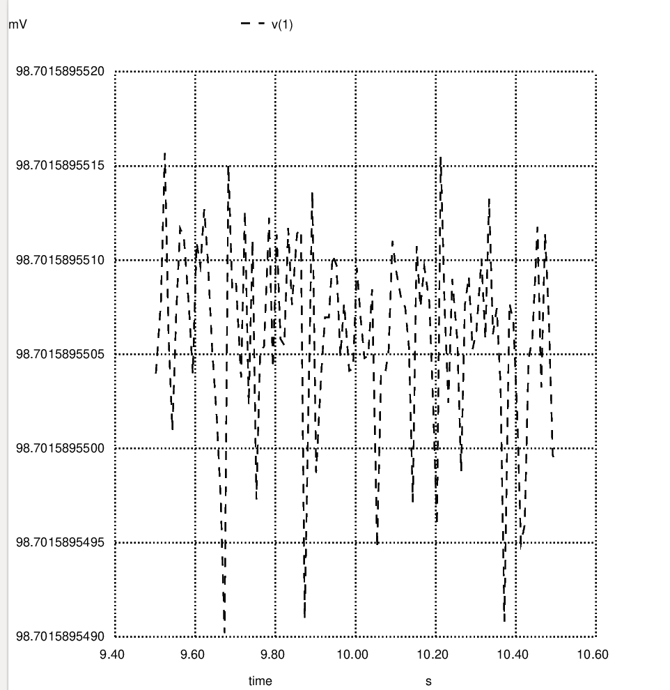
One command plots the postscript of the signal output. I normally plot a smaller interval at 1ms but here I'm plotting a larger interval to make it easier to see/read. The plot is representing the peaks here instead of the wave but you get the point. It's just not a stable waveform.

The second command I use to write the data to a vector file which I then later use to generate a .wav file so I can hear the oscilator.

.control
op

tran 10ms 10.5s 9.5s
hardcopy postscript/multivibrator.ps V(1)

tran 1ms 1s
wrdata vectors/multivibrator v1#branch

.endc

Here's the plot of the output:

enter image description here

\$\endgroup\$
4
  • 3
    \$\begingroup\$ You should include the circuit, use the schematic entry tool that is available when you edit your question. A general tip is to set the "maximum timestep" option (I am not exactly shure what that option in called in your nGSpice) such that at least 1000 time points are simulated. Note how your outout has basically no variation, it is 98.7 mV. So what you're seeing is "numeric noise" (not oscillations!) and not the circuit's behavior. \$\endgroup\$ Commented Jun 1, 2021 at 12:54
  • \$\begingroup\$ I agree, whole scale is 1-2nV, far below the noise floor. \$\endgroup\$
    – rdtsc
    Commented Jun 1, 2021 at 13:15
  • \$\begingroup\$ The schematic is a negative with dark blue lines on a black background that are almost impossible to see. I tried converting it to a positive image but the lines disappeared. \$\endgroup\$
    – Audioguru
    Commented Jun 1, 2021 at 17:23
  • \$\begingroup\$ R2 & R3 should be max ~ R1*(beta/10). (100k is too high). Exactly symmetrical values don't work often in simulator. \$\endgroup\$
    – Antonio51
    Commented Nov 7, 2021 at 15:29

1 Answer 1

4
\$\begingroup\$

Generally you need to include some initial disturbance to get the oscillator going.

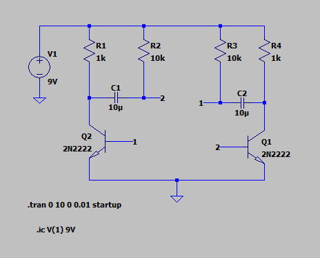
In LTSpice you can use the "startup" and ".ic" (initial condition) directives to create that disturbance.

Here is an example:

enter image description here

The "startup" directive tells LTSpice to start the DC supply at 0V.

The ".ic" (initial condition) directive sets the initial voltage at node 1 instead of the voltage found by performing the DC analysis.

Without these directives this simulation does not oscillate.

If ngspice does not support the "startup" directive, I would try replacing your DC supply with a step function.

Update: The disturbance might not have to be very large. In this above example I've found the voltage in the ".ic" directive can be made as low as 0.0000001V (0.1uV). Going to 0.01uV doesn't work, though.

\$\endgroup\$
2
  • \$\begingroup\$ That was it... works now, thanks! \$\endgroup\$
    – richie
    Commented Jun 1, 2021 at 20:50
  • \$\begingroup\$ Just a note: uic and startup are not the only ones that guarantee oscillations. Adding a slight imbalance to one of the base resistors, for example, will let the oscillations build up. If the simuation time is much larger than an initial oscillation period (for the build-up), then an imposed timestep is needed. For this case, try modifying R2 to be 10k1 and let the smulation run as .tran 0 10 0 0.1m (where the 0.1m is needed for the initial build-up, you can see if you zoom in). \$\endgroup\$ Commented Jun 2, 2021 at 6:16

Your Answer

By clicking “Post Your Answer”, you agree to our terms of service and acknowledge you have read our privacy policy.

Not the answer you're looking for? Browse other questions tagged or ask your own question.