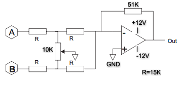
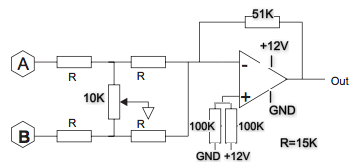
In the second schematic, the non-inverting input is referenced to Vcc/2, while the inverting input is referenced to GND. There is a 6 V DC difference in potential between the two opamp inputs. Trying to amplify this is saturating the output stage.
To fix this:
Connect the pot wiper to the junction of the two 100K resistors. << Reference Designators! >>
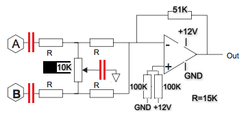
Add two decoupling capacitors from that node to GND, a 0.1 uF ceramic and a large value electrolytic. This node has to look like zero ohms at all audio frequencies. The electrolytic cap value is based on the lowest possible combined impedance of the pot and the four R resistors.
Add decoupling capacitors across the opamp power supply pins. Analog Devices often shows two caps in parallel, a 0.1 uF ceramic and a 10 uF electrolytic.
Add input coupling capacitors.


