I have a 6 V solar panel and a bunch of TP4056 modules with the battery protection circuits lying around and I thought I'd use them to make a solar powered BLE circuit with the nRF52840 dongle for some future projects as also have a couple of those lying around.
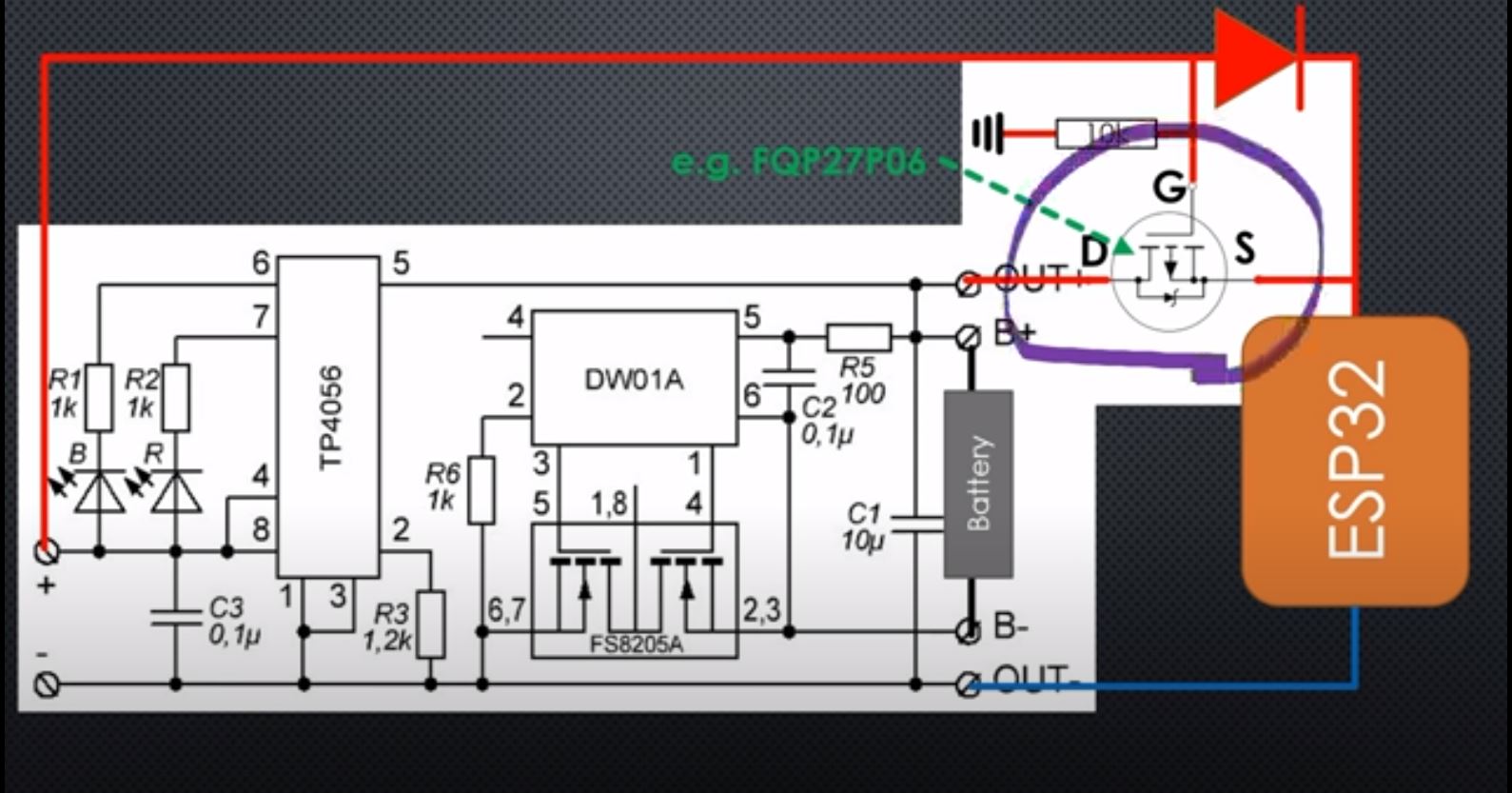
The project was inspired by a solar charging circuit from one of Andreas Speiss's videos (https://www.youtube.com/watch?v=37kGva3NW8w) where he added a "power path" so that the load (in my case the nRF52840) runs directly on solar when there is sunlight instead of discharging the battery. However, I don't quite understand how the circuit works and I was hoping that someone here could provide an explanation.
If I have understood correctly P-channel MOSFET will only conduct when the voltage difference between the gate and the source is negative. So when there is full sun the solar panel will output 6 V and the source voltage will then be 6 V minus the drop across the Schottky diode. Vgate - Vsource will be positive and the P-channel FET will act as an open circuit.
However, I don't understand how the circuit works when there is no sun, i.e. Vgate = 0 V. Won't the source voltage also be 0 in that case, i.e. Vgate - Vsource = 0 V and still act as an open circuit? The source voltage would have to be 2 V in order to reach the gate threshold voltage. Will Vsource be the same as the battery voltage? If yes, can someone explain why? I am probably missing something fundamental here so please bear with me.
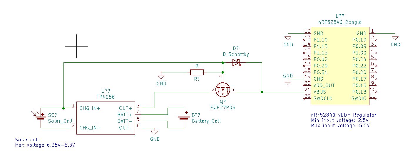
There is also a second issue that I would like to get some advice on. The nRF52840 has an internal regulator that has a minimum input voltage of 2.5 V and max 5.5 V. Now the 6 V solar panel will actually output ~6.25-6.3 V in full sun (based on measurements) so I was wondering what the best way to limit the voltage to max 5.5 V, while still being able to power the nRF52840 with solar down to 2.5 V.
I came a cross this What is the best way to limit voltage of a solar panel? question, which initially suggests using a shunt voltage clamp. Going through the comments it would seem that a LDO wont have to dissipate as much energy as the shunt voltage clamp. So do you think its better to go with a LDO with a minimum input voltage of 2.5 V, max 6.5 V and a 5 V output voltage e.g. the MAX8867 (https://eu.mouser.com/datasheet/2/256/MAX8868-1389206.pdf)
I made a quick schematic in Kicad, but the circuit/component to limit the voltage to 5.5 V or below is missing as you can see.


