1
\$\begingroup\$

Would the series inductance and shunt capacitance of a theoretical, lossless transmission line create signal attenuation? If so, how much and how could I calculate it?

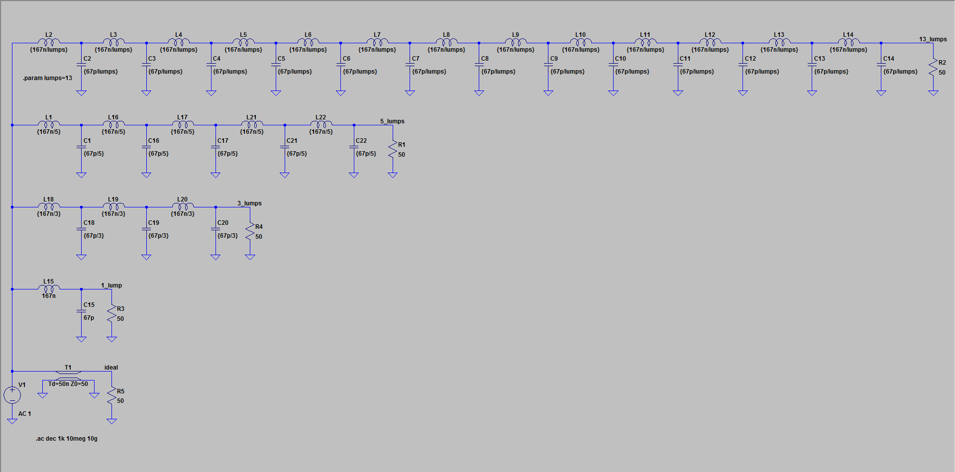
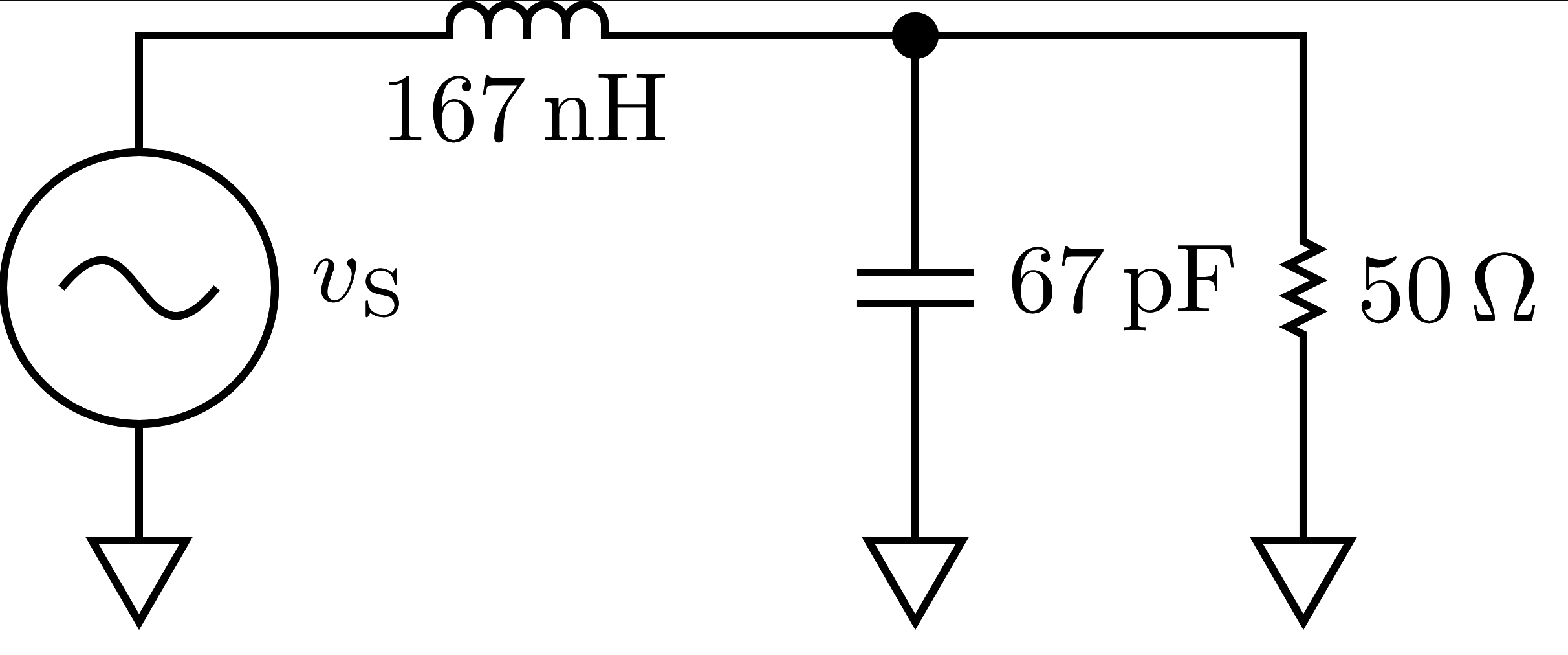
Imagine an ideal, lossless transmission line connected between an ideal voltage source (0 output impedance) and a perfectly-resistive 50ohm load. The transmission line can be modeled as a set of lumped series ideal inductors and lumped shunt ideal capacitors (remember, it's lossless, so there should be no resistive values). Let's use the lumped inductance and capacitance values provided by wcalc here. This calculator gives roughly \$167\,\text{nH/m}\$ and \$67\,\text{pF/m}\$. Let's take \$1\,\text{m}\$ of this cable so that the total series inductance is \$167\,\text{nH}\$ and shunt capacitance is \$67\,\text{pF}\$. The total equivalent circuit is then shown in the schematic below.

enter image description here

Imagine our signal frequency to be \$1\,\text{GHz}\$.

I would then expect the gain of this circuit (the output voltage is measured across the resistor and the input voltage is the voltage from the source) to be approximately \$-53\,\text{dB}\$.

I used the following python code to calculate the gain:

import numpy as np

frequency = 1e9
omega = 2 * np.pi * frequency
inductance = 167e-9
capacitance = 67e-12
zl = 1j * omega * inductance
zc = 1j / (omega * capacitance)
z1 = zl
z2 = 1 / (1 / zc + 1 / 50)

g = 1 / (1 + z1 / z2)
g_db = 20 * np.log10(np.abs(g))
print("gain: {:.0f} dB".format(g_db))

Is this calculation correct? The signal loss seems very excessive to me. If I erred somewhere in the analysis (which I expect I did), can you point out where I went wrong?

\$\endgroup\$

2 Answers 2

1
\$\begingroup\$

The calculation is correct. The analysis is well...not technically wrong but a bit misguided. Let's start by highlighting this statement in your question:

The transmission line can be modeled as a set of lumped series ideal inductors and lumped shunt ideal capacitors (remember, it's lossless, so there should be no resistive values).

This is saying that a transmission line, which uses the concept of "distributed" elements, can be modeled as "lumped" elements. The limitations of this type of modeling are what's missing in your understanding. You can approximate a line using lumps, but the resultant accuracy is highly dependent on the # of lumps...especially at higher and higher frequencies. The theory is that the ideal line is modeled as the # of lumps \$\rightarrow \infty\$.

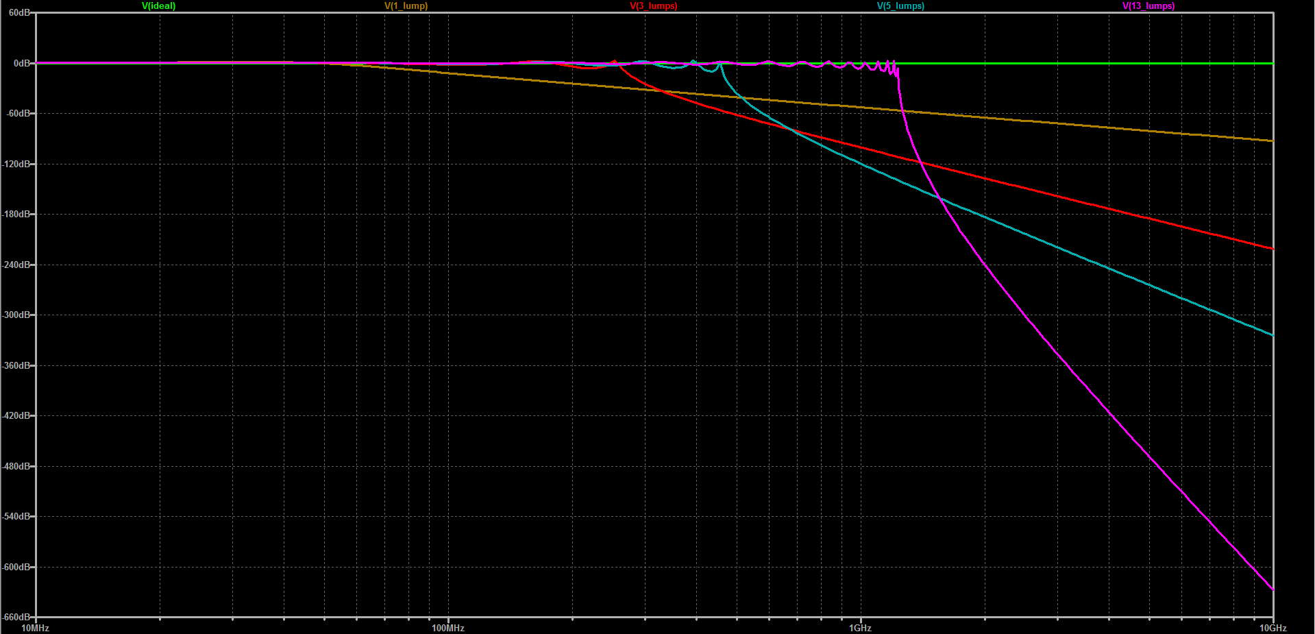
You chose the number of lumps to be equal to 1...which is a tad less than \$\infty\$. I played around in SPICE and found that I can get somewhat decent flatness at and around 1GHz if I use 13 lumps. I plotted a few different "# of lumps" to show the difference, as shown below.

enter image description here

enter image description here


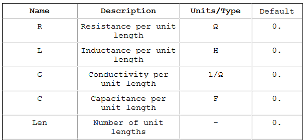
Since we're already in SPICE, I'd like to point out a nice tool you can use for modeling distributed elements if you already have the "per unit length" values. The component in LTspice's library called ltline (lossy transmission line) uses the SPICE3 LTRA model which takes the following main parameters:

enter image description here

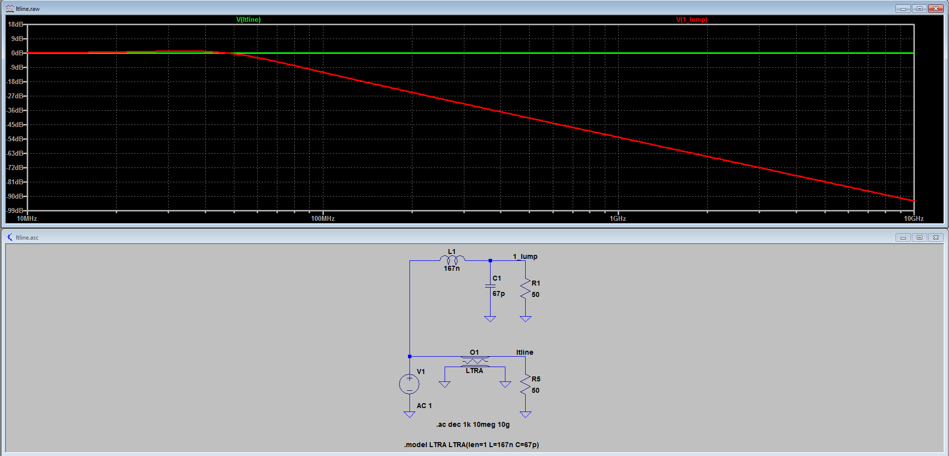
If we use this model for your problem (we only need L, C and len), we can get a nicer result without using 13 lumped elements taking up twice your screen width.

enter image description here

\$\endgroup\$
1
\$\begingroup\$

Imagine our signal frequency to be 1GHz

1 GHz has a vacuum wavelength of about 30 cm and, if you use anything remotely close to 30 cm as your equivalent lumped-length then you will come unstuck.

Let's take 1m of this cable so that the total series inductance is 167nH and shunt capacitance is 67pF.

You have fallen into the trap and come unstuck. Try making the lumped-element length equivalent to about 1 cm (about one tenth of one quarter wavelength).

\$\endgroup\$

Your Answer

By clicking “Post Your Answer”, you agree to our terms of service and acknowledge you have read our privacy policy.

Not the answer you're looking for? Browse other questions tagged or ask your own question.