I need to write a matlab code for a power flow analysis using the Gauss-Seidel method. I have done the first part of the question, but I cannot figure out how to do the second one.
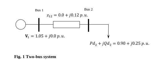
The figure given on the assignment is the following:

The question asks for a code to be written for a power mismatch tolerance of Ep=10^(-6) and max(|ΔP2|,|ΔQ2|)<Ep.
The code I've written so far is the following:
% In the following code the Gauss-Seidel method will be used in both parts
% (1) and (2) to calculate the power flow in a two-bus system.
% Bus 1 is a slack bus, for which the voltage and angle are given.
% Bus 2 is a PQ bus, for which the load power is given, but the voltage and
% angle need to be computed.


% Part (1):
% In this section, the power flow solution to be found has a voltage
% convergence tolerance of Ep =1e-6, with max |Vi(k+1)-Vi(k)|< Ep.

% Formation of the matrix for the bus admittance:
% The transmition impedance between buses 1 and 2 is z12 = 0.0 + j0.12 p.u.
% therefore:
z12=0.0+1i*0.12;
% y12 = 1 / z12
y12=1/z12;
Y11=y12;
Y12=-y12;
Y21=Y12;
Y22=y12;

% Formation of power injections:
PQ=[]; % the bus number is represented by the number in the brackets, i.e.
       % PQ(1) is for bus 1, and PQ(2) is for bus 2
% The load at bus 2 is 0.90 + j0.25 p.u., thus the power injection is:
PQ(2)=-0.90-1i*0.25;

% The follwoing are the symbols of the power flow solutions' values:
VK=[];
VK1=[];
IK=[];

% The voltage at bus 1 is:
VK(1)=1.05+1i*0.0;
VK1(1)=1.05+1i*0.0;

% The voltage at bus 2, where the flat start is, is the following:
VK(2)=1.0+1i*0.0;
VK1(2)=1-0+1i*0.0;
% Also, the current at bus 2 starts at:
IK(2)=0.0+1i*0.0;

%Convergence tolerance format:
EP=input('Convergence Tolerance, EP:');
fprintf('\n');
fprintf('%12.5e\n', EP);

%Following are the Gauss-Seidel iterations:
for k=1:1000
% The current at bus 2 is calculated according to the equation: IK(2) =
% conjugate ((P(2) + jQ(2)/VK(2)), so:
IK(2)=conj(PQ(2)/VK(2));
% The voltage at bus 2 (which is the PQ bus), is given by the equation:
% VK1(2) = VK+1(2)/Y22, where VK+1(2) = (IK(2)-Y21xV1,therefore:
VK1(2)=(IK(2)-Y21*VK1(1))/Y22;
fprintf('The number of iterations is the following: %4i max|VK+1-VK|=%12.5e.\n The voltage magnitude at bus 2 is: %12.9e.\n The voltage angle at bus 2 is equal to: %12.9e.\n',k,abs(VK1(2)-VK(2)),abs(VK1(2)),angle(VK1(2))*180/pi);
% Convergence calculation:
    if (abs(VK1(2)-VK(2))>=EP)
    % In the case max|VK+1-VK|>=EP, then stop:
        break;
    else
    % In any other situation, the iteration should be continued, and the
    % solution, for which VK=VK+1, should be updated:
        VK(2)=VK1(2);
    end
end

% The current injection at bus 1 (slack bus) is:
IK(1)=Y11*VK1(1)+Y12*VK1(2);
% The power injection at bus 1 is determined using the form:
PQ(1)=VK1(1)*conj(IK(1));

% Printing the output power injections (active and reactive), at slack
% bus 2:
fprintf('Reactive power injection at bus 2: %12.5e. Active power injection at bus 2: %12.5e\n', real(PQ(1)), imag(PQ(1)));


% Part(2):
% In this section, the power flow solution to be found has a voltage
% convergence tolerance of Ep =1e-6, with max (|ΔP2|,|ΔQ2|)< Ep.
I am new to power flow analysis and matlab so helping me with this would be extremely useful. Is there any part of the code that I've written so far that I should use for the second part, and also, how will I calculate ΔP2 and ΔQ2. Thanks in advance.

