7
\$\begingroup\$

I was instructed to set up a resistor on the negative side of the LED and pulling it to ground. I'm confused why we are implementing a resistor on the backside (negative end) of the LED. I always thought we put resistors before our load (LED) to limit/control current flow. Therefore, I'm confused why we are putting the resistor between the cathode (negative end of LED) and ground. To me it seems like this resistor isn't doing anything.

I don't know if it helps but on my board the positive side of the LED is connected to PIN 13 and the negative (cathode) end is going to the resistor then to the ground on the breadboard then to the ground pin on the Arduino board.

I apologize for the picture as it's the best I can get it at the moment with what I have available to me.
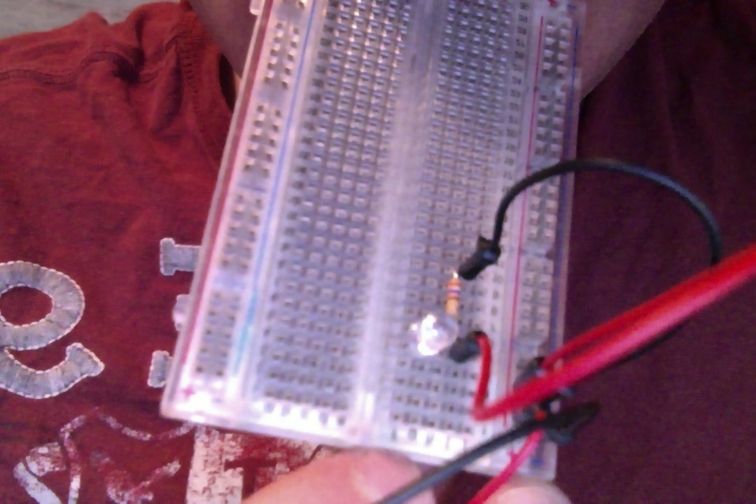
enter image description here

\$\endgroup\$
1
  • \$\begingroup\$ I've been wondering this same thing myself! All of the tutorials in the Starter Guide have this set up if they use an LED. \$\endgroup\$
    – jlewkovich
    Commented Dec 19, 2014 at 22:35

3 Answers 3

4
\$\begingroup\$

While driving a load with a microcontroller, you may add resistors on either side. This is because the current entering the LED and leaving out of the LED is the same. So if a resistor is used on the high side or low side, it would limit the current. They can be used on either side and either way because they are not polarized.

In such configurations, resistors limit current flowing through an active component (LED in your case). Considering Kirchoff's Law, it doesn't matter if the resistor is on the positive or the negative side of the LED. It would limit the same amount of current irrespective of the positive side or negative side of LED.

More reading: Kirchhoff's Laws

\$\endgroup\$
1
  • 4
    \$\begingroup\$ -1 The order in the circuit has nothing to do with resistors not being polarized. \$\endgroup\$
    – starblue
    Commented Feb 10, 2013 at 9:20
3
\$\begingroup\$

For the current the order of the resistor and the LED doesn't matter. The current has to flow through both, so the voltages on the elements resulting from the current on each element are the same. Independently of the order they add up to the same total voltage, because addition is commutative.

That would change if you were interested in the voltage at the connection between the resistor and the LED. For example, with a resistor between the cathode of the LED and ground it is relatively easy to measure the current, using the voltage and the known value of the resistor.

\$\endgroup\$
1
  • \$\begingroup\$ It's easy to measure the current if the resistor isn't connected to ground, also. Either way, simply put the leads of a voltmeter across the resistor. \$\endgroup\$
    – Phil Frost
    Commented Feb 10, 2013 at 13:23
2
\$\begingroup\$

The order of components in a series circuit does not matter [1]. Consider a hydraulic analogy: a wire is like a hose, a diode is like a check valve, and a resistor is like a pinch in the hose that restricts flow. You want to limit the current (water) that can flow in the hose. Does it matter where you pinch it?

[1] at least, not until the speed of light is slow relative to the operation of the circuit. See How does the current know how much to flow, before having seen the resistor?

\$\endgroup\$

Your Answer

By clicking “Post Your Answer”, you agree to our terms of service and acknowledge you have read our privacy policy.

Not the answer you're looking for? Browse other questions tagged or ask your own question.