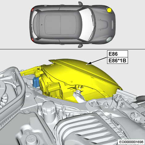
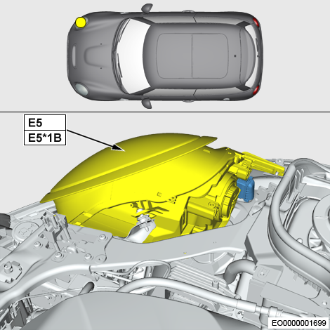
I am in the process of upgrading my headlights on my Mini. I currently have the halogen units, and I'm retrofitting LED units.
One of the differences is that the LED units require connecting to the K-CAN.
I'm aware the standard calls for twisted pair connection, terminated with 120ohm resistors.
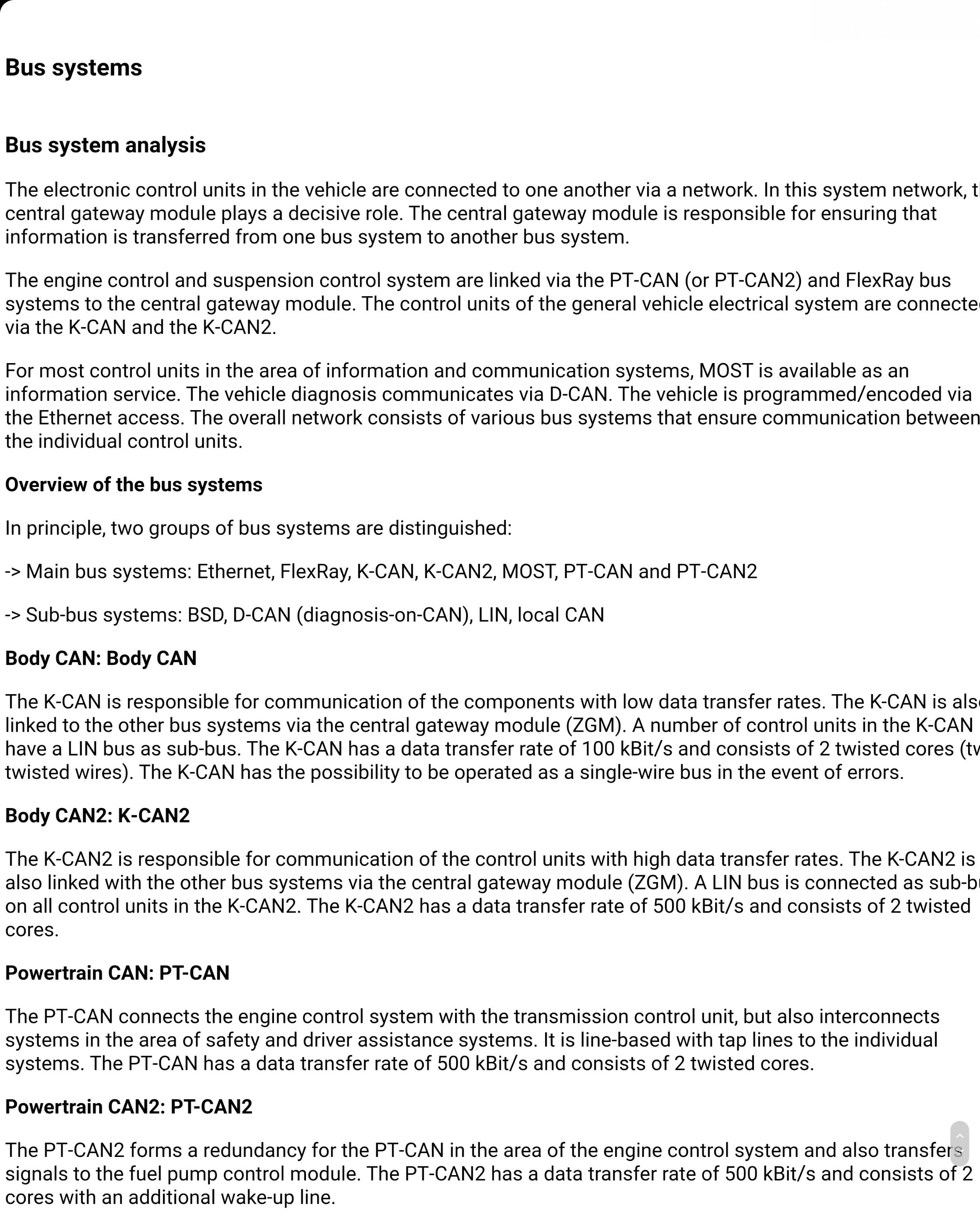
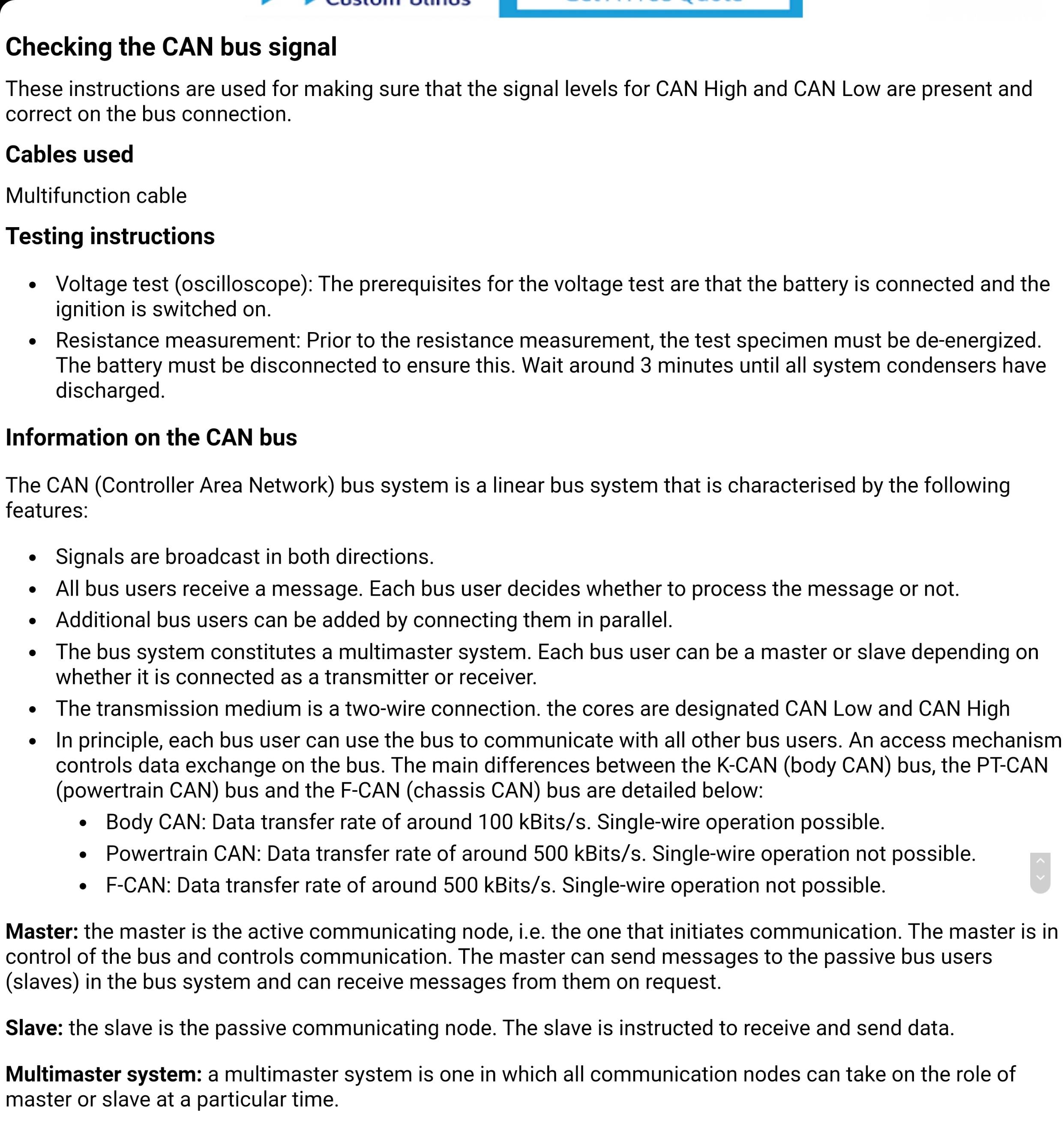
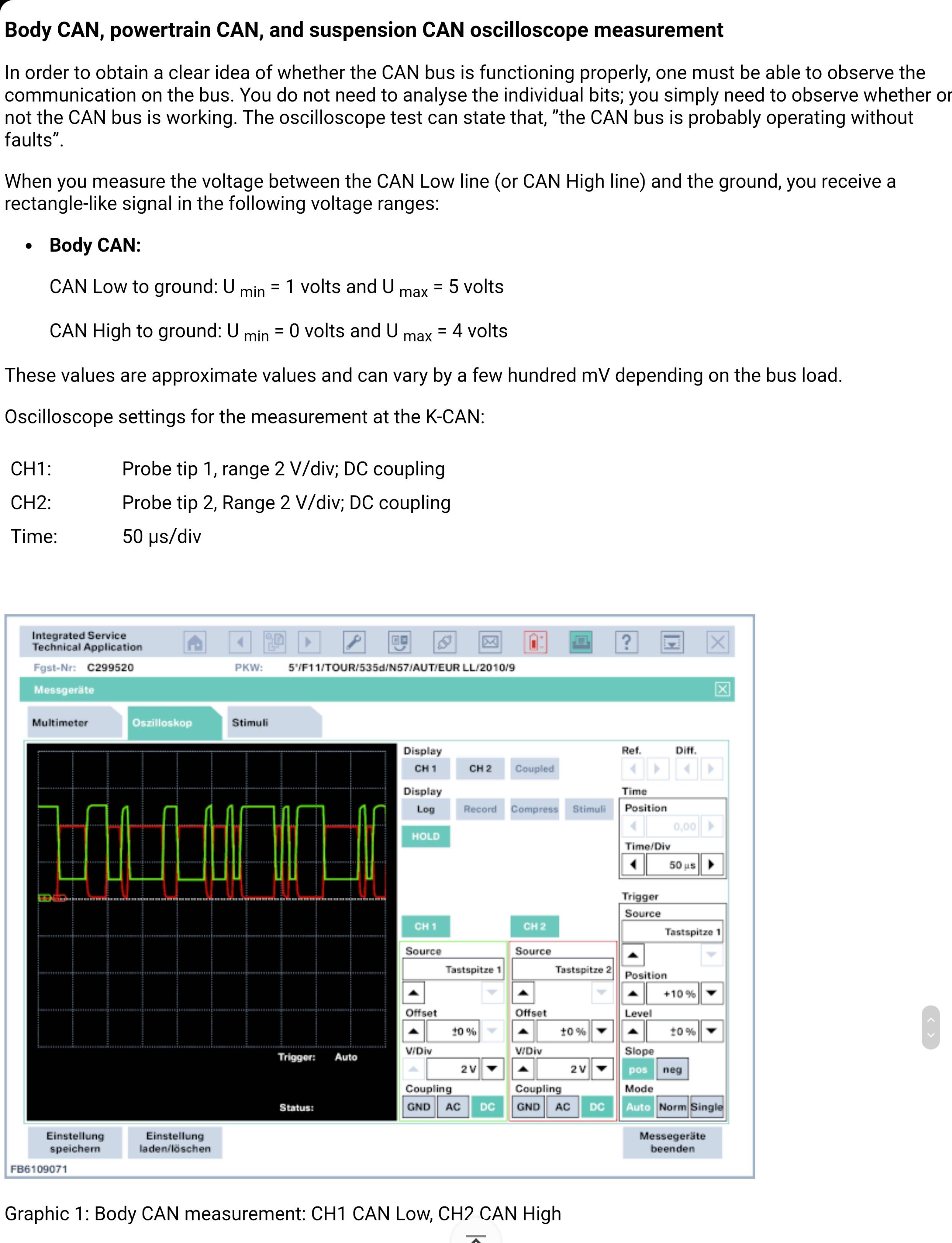
According to the BMW documentation, the body CAN (K-CAN) operates at 100 kbps.
Some people who have done this mod, have done so without running twisted pairs, simply reusing the existing wiring.
Question number 1 is how stable would this connection be if run on UNTWISTED pairs? I would rather run a twisted pair, but the work involved in insulating and waterproofing it, and getting it through the bulkhead and properly routed is massive. Reusing the existing wires, although not to standard, would be much easier, if the connection would be reliable enough.
Question number 2 regards the way in which I connect into the existing canbus, regardless of twisted or untwisted pairs.
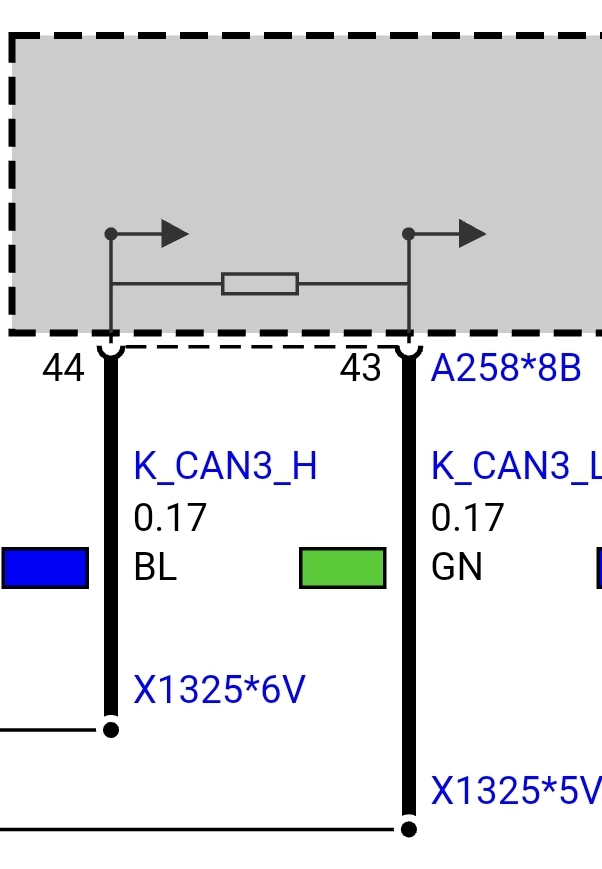
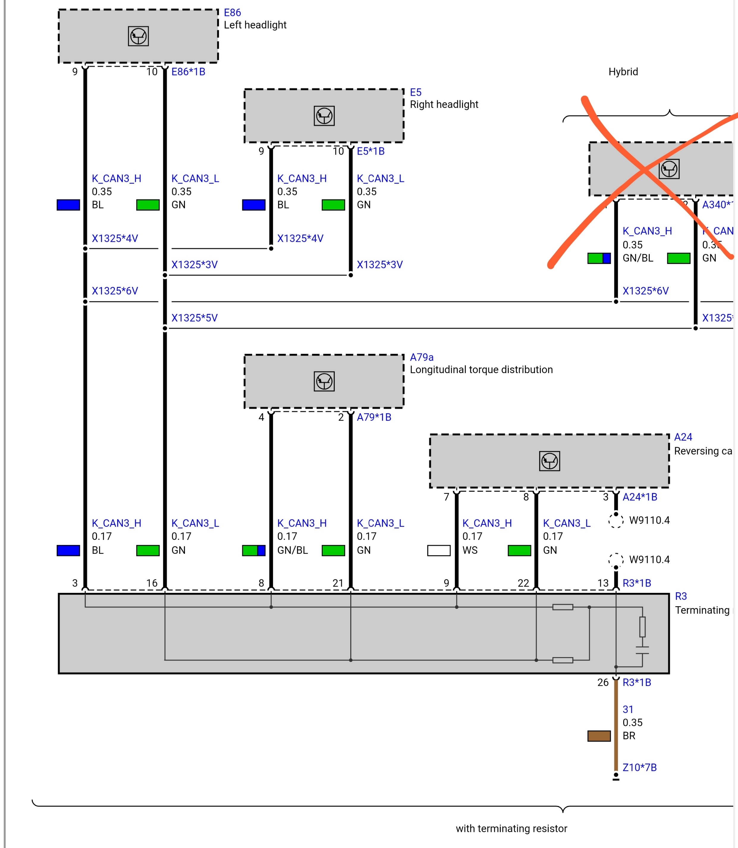
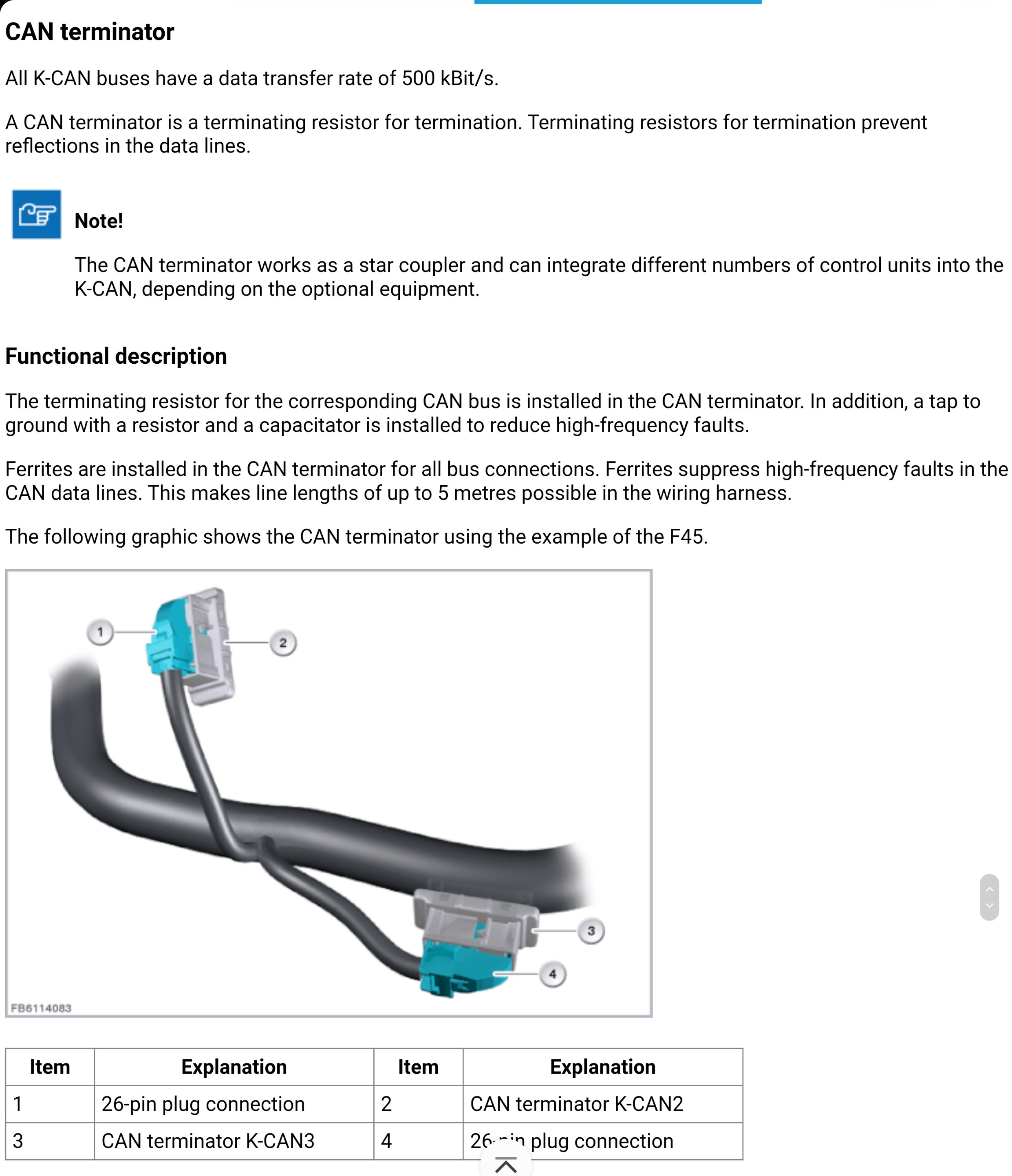
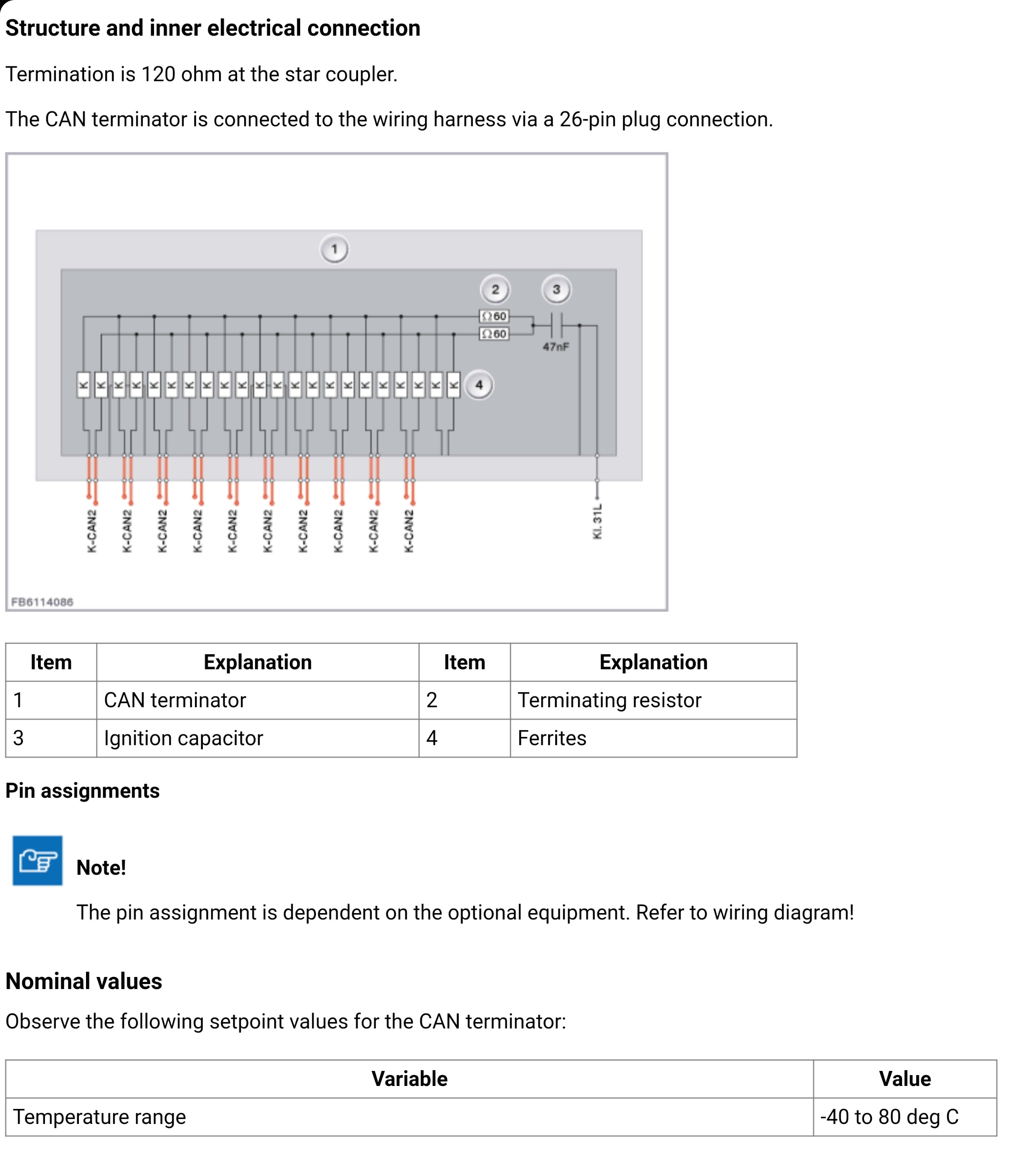
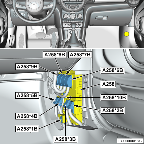
At the moment, the CAN BUS wiring runs straight from the BDC to the terminating resistor, R3, in the rear of the vehicle. Then connected to R3 are the Longitudinal Torque Distribution and the Reversing Camera.
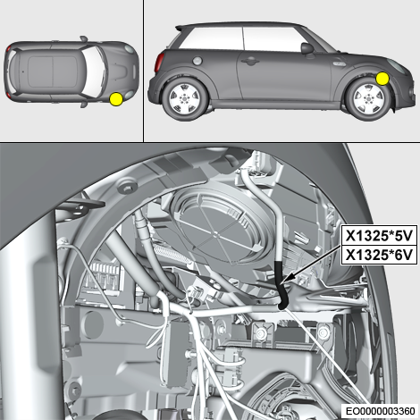
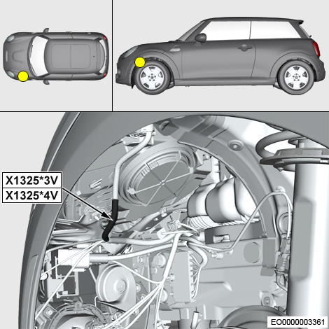
Had the headlights be factory fitted, then according to the wiring diagram, the CAN BUS wiring would split at location X13255V and X13256V, and head to 1 headlight, with a further splice at X13253V and X13254V heading to the other headlight. So I know a parallel connection is viable.
Additionally, I'm adding a pair of spot lights that also need to connect to the same CAN BUS.
What is the best way to add THREE wires to each of the CAN BUS lines?
I do have a spare terminating resistor which has 10 pairs of connection points, but I'm worried this would skew the impedance on the BUS.
EDIT Adding all the CAN BUS info I have

