0
\$\begingroup\$

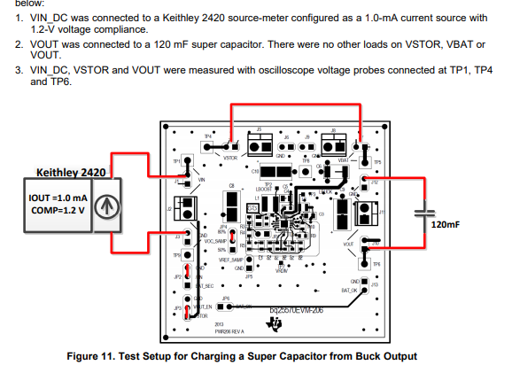
I have a power source that can give me around 0.9 ~ 1 V and 900uA. I would like to use the BQ25570 battery charger evaluation module to give an output of 1.8 V. I would like to attach a capacitor to discharge the current at 1.8 V. I looked at the manual, but it only discusses how to set it up as a buck converter.

enter image description here

How can I set it up to increase my voltage while charging the capacitor?

\$\endgroup\$
8
  • 1
    \$\begingroup\$ That’s not even enough power to light an LED unless you have a boost harvesting IC \$\endgroup\$
    – D.A.S.
    Commented Jul 28, 2021 at 17:16
  • \$\begingroup\$ It is for low power application and I want to store current in a capacitor and then release it \$\endgroup\$ Commented Jul 28, 2021 at 17:17
  • \$\begingroup\$ First you must store current in two large inductors then release it slowly into a supercap with two very low voltage switches by alternating charge/discharge \$\endgroup\$
    – D.A.S.
    Commented Jul 28, 2021 at 17:19
  • \$\begingroup\$ Think how you can simulate a match load to source impedance of Voc/Isc using a switched inductor with an astable oscillator. \$\endgroup\$
    – D.A.S.
    Commented Jul 28, 2021 at 17:26
  • \$\begingroup\$ The main challenge is first to use the current harvesting chip to boost up the voltage first. so I can operate on the output of it. \$\endgroup\$ Commented Jul 28, 2021 at 17:35

1 Answer 1

0
\$\begingroup\$

The buck converter is operated from the energy stored at a higher voltage on VSTOR. It isn't intended to drive the consumer directly. It charges VSTOR to 4.2V, then uses the buck converter to make 1.8V for the consumer. The chip has a programmable threshold - when VBAT rises above the threshold, the 1.8V output is enabled.

\$\endgroup\$
4
  • \$\begingroup\$ If I am using my low voltage power source as Vin and 1000uF capacitor as current discharger at V_store which feels that it is the same as V_out? Do I need another voltage source for bias? if not, won't that deplete my power source? \$\endgroup\$ Commented Jul 28, 2021 at 18:36
  • \$\begingroup\$ 1000 uF might not have the leakage specs unless rated for. HV, , try > 10uF \$\endgroup\$
    – D.A.S.
    Commented Jul 28, 2021 at 21:53
  • \$\begingroup\$ How do I set up the threshold of the input to operate my output on the 1.8 V? How would I tell the chip that if the input is 0.9V start working because as it is right now my input has to be 3V (using a jumper from JP6 to JP3) \$\endgroup\$ Commented Jul 29, 2021 at 17:22
  • \$\begingroup\$ @AnwarElhadad: Refer to pages 15 and 16 of the BQ25570 datasheet. That section explains how to set the levels with various resistor combinations. \$\endgroup\$
    – JRE
    Commented Jul 29, 2021 at 17:51

Your Answer

By clicking “Post Your Answer”, you agree to our terms of service and acknowledge you have read our privacy policy.

Not the answer you're looking for? Browse other questions tagged or ask your own question.