3
\$\begingroup\$

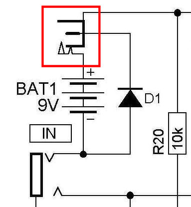
unknown symbol

I am in the process of designing a filter based upon the Korg CMP-1 / Yamaha CMP-1 Compressor Pedal, for use in my home built Analog Synthesizer.

In the schematic, attached to the battery pos terminal is a symbol I am not farmiliar with, and I have been unable to find any reference to this symbol. At first I thought it may be a simple heatsink, but now I am wondering if it is a symbol for an attached ''Reference Voltage'' electronics.

Has anyone have any knowledge of this symbol and what it refers to.

Thanks in advance for any assistance.

Lance.

\$\endgroup\$

2 Answers 2

7
\$\begingroup\$

A centre-negative socket for an external DC source that disconnects the battery when inserted.

\$\endgroup\$
2
  • \$\begingroup\$ NMF - A DC socket seems the most logical component, I don't know why I didn't think of it myself. Thank you for your quick response. \$\endgroup\$
    – Lance Arn
    Commented Aug 9, 2021 at 9:34
  • \$\begingroup\$ The common term is "barrel jack". The one shown has a switching contact that disconnects the battery when a plug is inserted. \$\endgroup\$
    – Dave Tweed
    Commented Aug 9, 2021 at 11:43
1
\$\begingroup\$

That's a barrel jack receptacle.

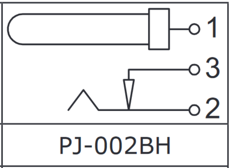
Here's a more easily understood symbol (though the 1-3-2 pin ordering is slightly confusing):

schematic symbol

from this datasheet of a common part of that type. It's a physical representation of the component. Pin 1 in the symbol above is the center pin. When the barrel is removed, a spring connected to pin 2 physically moves upwards, and makes contact with pin 3. When the barrel is inserted, the pin 2 spring is pressed away from pin 3, opening the switch.

As seen in your schematic, you can use this to make a simple battery power/wall adapter mux by connecting your battery to pins 1 and 3 and connecting pins 1 and 2 to your Vcc and GND nodes. When the adapter is unplugged, current can flow through your battery, through pin 3, through the internal switch, and through pin 2. When the adapter is plugged in, pin 3 becomes disconnected, and current flows through the adapter and through pin 2, saving battery power while wall power is available.

Without this feature, you'd need a mux IC or pair of diodes with attendant noise and losses.

\$\endgroup\$
1
  • \$\begingroup\$ Thanks for this clarity. This is the symbol I was expecting to see in the schematic, as so this much clearer now.. \$\endgroup\$
    – Lance Arn
    Commented Aug 12, 2021 at 2:49

Your Answer

By clicking “Post Your Answer”, you agree to our terms of service and acknowledge you have read our privacy policy.

Not the answer you're looking for? Browse other questions tagged or ask your own question.