1
\$\begingroup\$

I'm working on an MP3 player PCB based on an ESP32. I would like it to run on a battery.

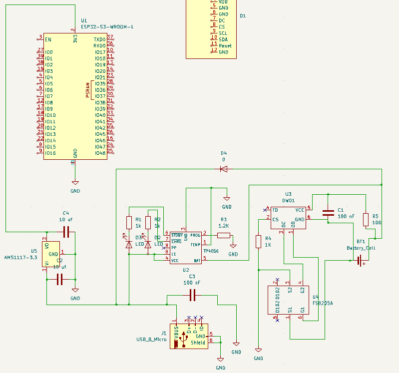
I have looked for a TP4056 with protection schematics on OSHWLab. This is my schematic:

enter image description here

Do I need the blue wire if I want it to work with or without USB connection? Is this connection safe for the battery with the D4 diode?

I found a schematic where the connections OD->G1 and OC->G2 are switched. What is the correct connection?

EDIT : Based on Antonio Answer, the OD OC connection are good on mine schematic. What about the blue connection usefullness and security for battery ?

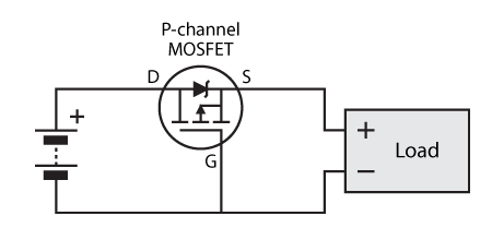
EDIT : If I change the D4 diode for a P-channel mosfet, do I use this schematic reversing the mosfet (mirror on X axe) ? enter image description here
Is this new LDO good ? XC6210B332MR Vin min : 1.5V Vin max : 6V Vout : 3.3 V

\$\endgroup\$
5
  • \$\begingroup\$ Here is what is commonly used forum.arduino.cc/t/tp4056-dw01a-li-ion-battery-charger-circuit/… \$\endgroup\$
    – Antonio51
    Commented May 5 at 18:36
  • \$\begingroup\$ Without the blue connection the battery will not power the MCU. And the diode is there to prevent that the battery is being charged and powering the load at the same time. When there are 5V in the USB rail, the diode is reverse biased. \$\endgroup\$
    – Gos
    Commented May 5 at 19:14
  • 1
    \$\begingroup\$ But, the AMS1117 will not work with one 3.7V battery. The drop out voltage of the LDO is about 1.2V, so it would need at least 4.5V to work. And the diode is adding a voltage drop. You should use another LDO and replace the diode by a P-channel mosfet. \$\endgroup\$
    – Gos
    Commented May 5 at 19:19
  • \$\begingroup\$ You can check in this post the explanation and how to set the mosfet: best-microcontroller-projects.com/tp4056-page2.html Also check the schematic of the module, it's what you are doing, more or less. \$\endgroup\$
    – Gos
    Commented May 6 at 7:03
  • \$\begingroup\$ XC6210B332MR should be Ok, I think. The drop out voltage (the difference between Vin and Vout), is smaller. So it should work with the battery voltages. \$\endgroup\$
    – Gos
    Commented May 6 at 7:16

1 Answer 1

1
\$\begingroup\$

There are many issues.

First of all, the charger is not able to charge the battery at all.

Second thing is, you need the blue wire or you have no path from battery to the music playing circuits. If you don't have the blue wire, you can only charge the battery but the battery has no load to power.

And since you must have the blue wire, then you also must have the diode, because you can't apply 5V from USB directly to battery, as that's why you have the battery charger.

The USB connector is also confusing. You seem to want to power this device and charge the battery from it, but you have connected it as host side connector, providing supply voltage out, signaling with ID pin that this is a host port but it should be an input to detect the role, and tied up D+ and D- to identify as a fast charging port to charge other devices.

\$\endgroup\$
3
  • \$\begingroup\$ I have update the usb port connection. I want to be able to power the ESP32 and charge the battery with the usb port. Why the charger (TP4056 ?) is not able to charge battery ? \$\endgroup\$
    – ewaca
    Commented May 5 at 20:37
  • \$\begingroup\$ @ewaca You are charging the battery through the 100 ohm resistor. \$\endgroup\$
    – Justme
    Commented May 5 at 21:25
  • \$\begingroup\$ You are right, I have update the schematic, it should charge now. Thank you. \$\endgroup\$
    – ewaca
    Commented May 5 at 22:44

Your Answer

By clicking “Post Your Answer”, you agree to our terms of service and acknowledge you have read our privacy policy.

Not the answer you're looking for? Browse other questions tagged or ask your own question.