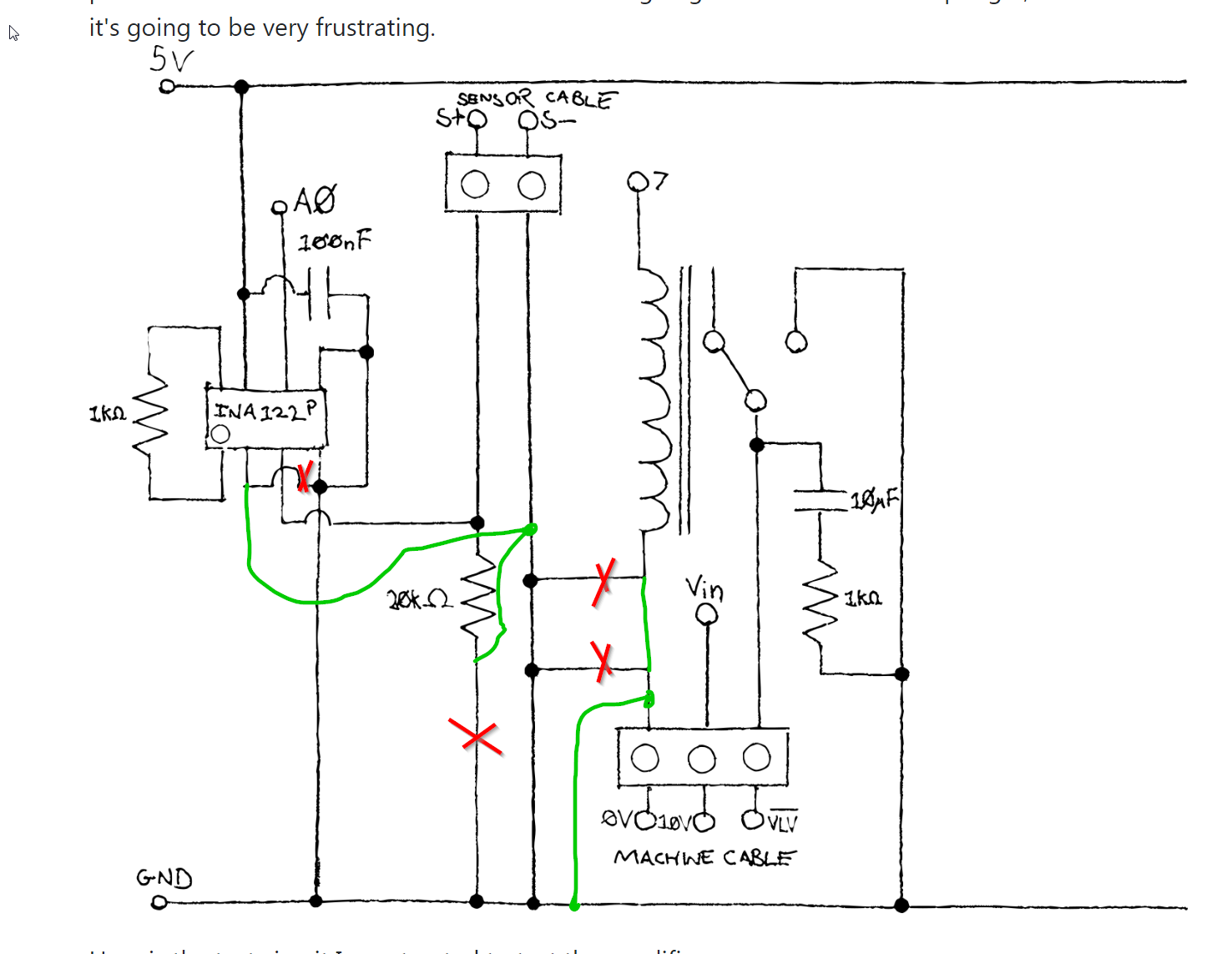
I built an Arduino Uno based control panel for an altitude training machine, which connects to an oxygen sensor. The value is amplified by an instrumentation amp (INA122P) and read into the analog input of the Ardiuno, which then decides whether to open the valve or not by controlling the VLV input to the machine. The machine connects to the control panel by 3 wires; 0V, 10V and valve control (valve opens when this is 0V, closes when floating) The 10V is supplied directly to the Arduino, which supplies the rest of my circuit with 5V. The oxygen sensor (medical oxygen sensor OOM202) is a micro fuel cell which outputs a voltage between 200μV and 20mV depending on the oxygen level. Because it generates its own power, the sensor output should be the same regardless of whether or not the machine is running.
I have confirmed that the output of my amplifier is exactly what I would expect given its input, and have also tested it with a test circuit designed to simulate oxygen sensor inputs and have confirmed that it is working as intended with a gain around 200.
However, in practice, I find that an output of 10.5mV from the oxygen sensor when the compressor is powered off jumps to around 12.5mV when it is powered on, and if the wire is disconnected from the oxygen sensor, theoretically meaning the voltage should pull down to 0V, it still jumps to around 10-12mV when the machine is powered on. I should note that the output of the amplifier gives the expected result for these inputs, but the inputs are clearly wrong.
Is this electrical interference and if so, how would I go about fixing it assuming that the oxygen sensor and altitude training machine cannot be changed?
I have considered moving the machine cable terminal block to a separate breadboard, but I'd prefer to have some idea of whether or not that's going to work before attempting it, as I'm sure it's going to be very frustrating.

Here is the test circuit I constructed to test the amplifier.

UPDATE: I troubleshooted the project as per the suggestions on this board, and I discovered that the problem was something I did not expect. The raw sensor value always jumps up when the machine starts, or when I put 5V into the amplifier circuit. I discovered that this stops happening if I remove the 20k ohm resistor (which is surprising, because the sensor's datasheet says the minimum load resistance is 10k ohm.)
I've got the circuit running pretty much as is without that resistor, although I'm now experiencing some power reliability issues when the relay clicks on. I had attempted to correct this issue by putting a 10uF capacitor on the relay output, but I'll try adding a larger capacitor across the supply voltage, which will hopefully store enough juice to keep the 7-segment display from dropping out.


