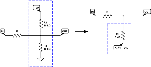
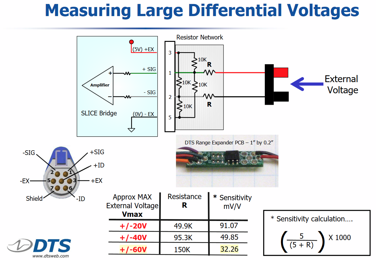
If you look carefully, each input consists of a circuit like this:
simulate this circuit – Schematic created using CircuitLab
On the right is the reduced version, after converting the components in the blue box to their Thevenin equivalent. From there it's easier to derive the relationship between the input signal \$V_{IN}\$ and output \$V_{OUT}\$:
$$
\begin{aligned}
V_{OUT} &= (V_{IN}-2.5V)\frac{5k\Omega}{R+5k\Omega} + 2.5V \\ \\
&= V_{IN} \frac{5k\Omega}{R+5k\Omega} + 2.5V(1-\frac{5k\Omega}{R+5k\Omega})
\end{aligned}
$$
It's clear that this configuration performs two functions:
Both the offset and attenuation help bring the input signal to within the acceptable input range of the differential amplifier that follows. If, for example, that amplifier (without any input conditioning) accepts input voltages from \$V_{MIN}\$ to \$V_{MAX}\$, then with this network in place the new range can be calculated by setting \$V_{OUT}\$ to those values, and finding the corresponding \$V_{IN}\$:
$$
\begin{aligned}
V_{IN} &= (V_{OUT} - 2.5)\frac{R+5k\Omega}{5k\Omega} + 2.5 \\ \\
V_{IN(MIN)} &= (V_{MIN} - 2.5)\frac{R+5k\Omega}{5k\Omega} + 2.5 \\ \\
V_{IN(MAX)} &= (V_{MAX} - 2.5)\frac{R+5k\Omega}{5k\Omega} + 2.5 \\ \\
\end{aligned}
$$
The difference between these two values will be the maximum allowable peak-to-peak amplitude of the input signal, with the extender network in place:
$$
\begin{aligned}
V_{IN(PP)} &= V_{IN(MAX)} - V_{IN(MIN)} \\ \\
&= (V_{MAX} - 2.5)\frac{R+5k\Omega}{5k\Omega} + 2.5 - (V_{MIN} - 2.5)\frac{R+5k\Omega}{5k\Omega} + 2.5 \\ \\
&= (V_{MAX} - V_{MIN}) \frac{R+5k\Omega}{5k\Omega}
\end{aligned}
$$
What this means is that where originally (with no extender) the maximum input amplitude was \$ V_{MAX} - V_{MIN} \$ peak to peak, now you can supply input voltages a factor of \$\frac{R+5k\Omega}{5k\Omega}\$ greater than that.
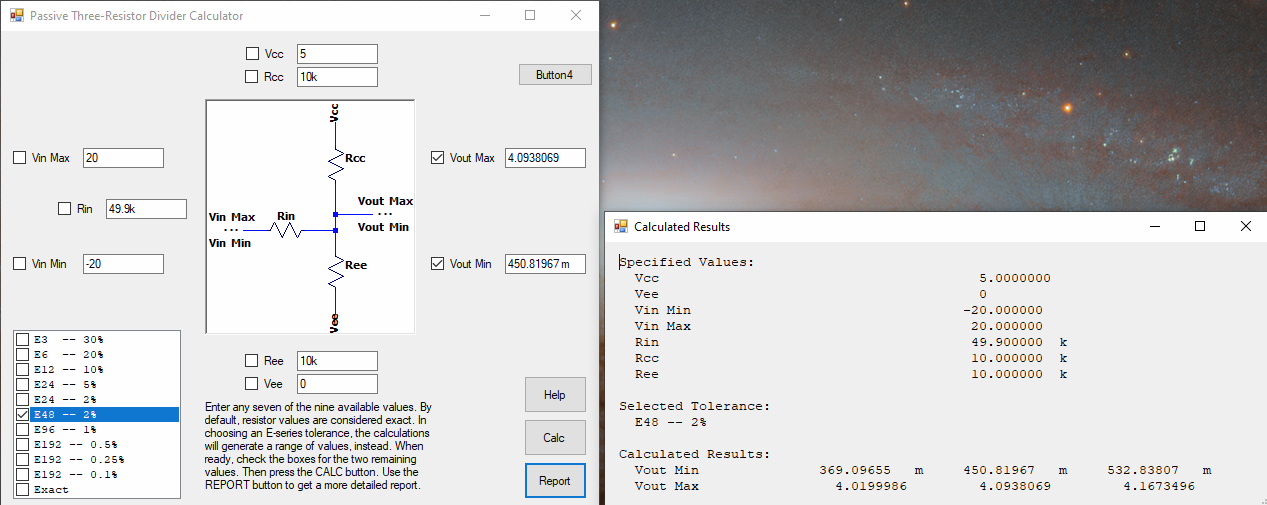
Real numbers might be more meaningful. For \$R=10k\Omega\$, \$V_{MIN} = 0V\$ and \$V_{MAX} = +5V\$:
$$ V_{IN(PP)} = (V_{MAX} - V_{MIN}) \frac{R+5k\Omega}{5k\Omega} = 15V_{PP}$$
The input must lie between:
$$
\begin{aligned}
V_{IN(MIN)} &= (V_{MIN} - 2.5)\frac{R+5k\Omega}{5k\Omega} + 2.5 = -5V\\ \\
V_{IN(MAX)} &= (V_{MAX} - 2.5)\frac{R+5k\Omega}{5k\Omega} + 2.5 = +10V\\ \\
\end{aligned}
$$
Here's a graph of what the input \$V_{IN}\$ (blue) might look like, and what the differential amplifier would see at one of its own inputs, \$V_{OUT}\$ (orange):
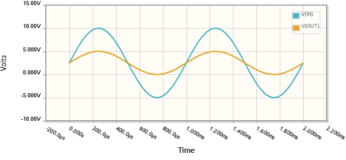
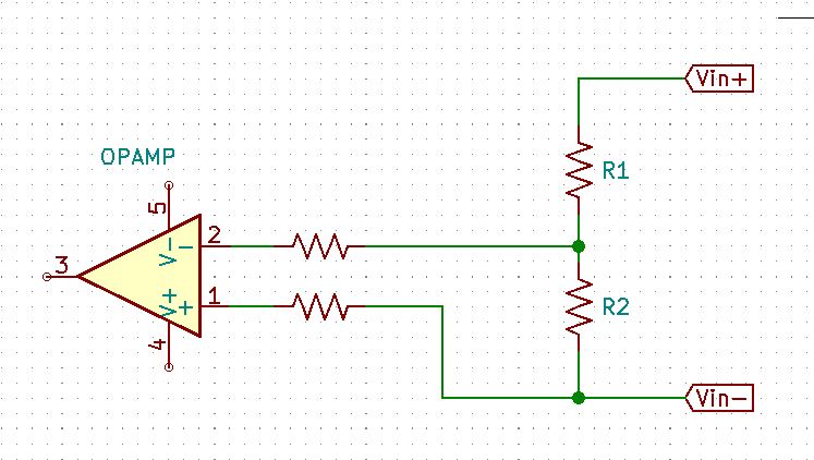
The differential amplifier has two such inputs, of course. With the same extender network at each input, what we are doing here is conditioning them both individually, but equally. As long as both inputs stay within \$-5V < V < +10V\$, then the amplifier will never see a voltage at either of its inputs outside of \$0V < V < +5V\$, and we never violate its own input constraints.

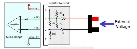


Ris to extend the input voltage range. \$\endgroup\$