0
\$\begingroup\$

This is my Schmitt Trigger design, which trips at \$2.3V\$ and \$1.7V\$-enter image description here
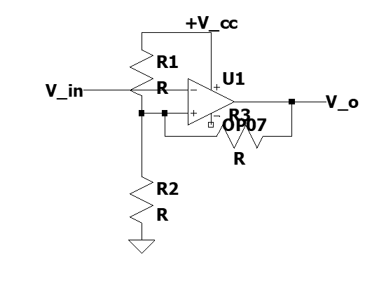
Here, $$+V_{cc} = 9V$$ $$R1 = 51k \Omega$$ $$R2 = 22k \Omega$$ $$R3 = 330k \Omega$$ \$V_{in}\$ is a square-wave with 0-7V peak to peak voltage. I'm expected to use a phototransistor along with a LED in order to provide variable voltage, with its base unconnected. This is to demonstrate the real life noise filtering of a Schmitt Trigger circuit using the phototransistor sensor. I don't know how to setup this circuit but I've tried in this way - enter image description here I've built this circuit on my breadboard. But, \$V_{in}\$ doesn't seem to turn D1 (LED) on. The series resistor R4 is of \$2k \Omega \$. Considering the forward voltage of a LED to be around \$2.2-3V\$, and \$V_{in}\$ as a square wave with \$1k Hz\$ frequency and \$0-7\$ pk-pk voltage, the LED should've turned on. What am I possibly doing wrong here? I've tried to scour for online articles regarding Schmitt trigger with noise sensor inputs, but haven't found anything. Can someone help me with this sensor circuit?
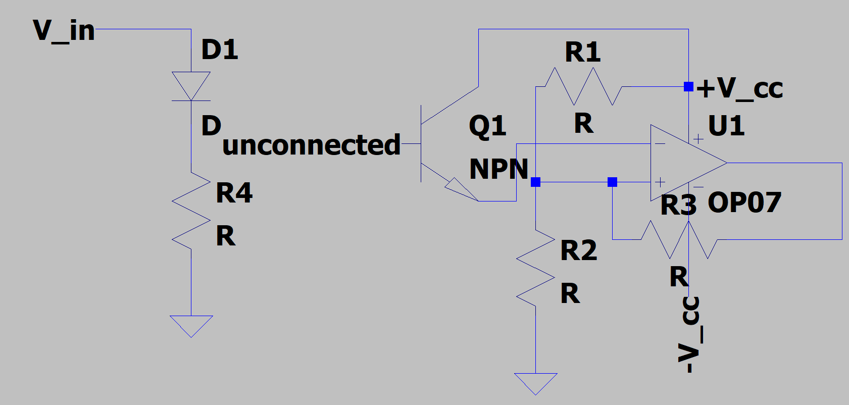
NOTE: The LED is required to shine light on the phototransistor's surface in order to activate it, so that the variable voltage obtained at its emitter is proportional to the intensity of light incident on it.

\$\endgroup\$
10
  • \$\begingroup\$ the circuit in the gray field has almost nothing in common with the first mentioned. In any case, it does not contain a Schmitt trigger. There is positive feedback, but once it is snapped it stays where it is. The other is Q1 is shorted or weakened by R1. Is that on purpose? \$\endgroup\$
    – arnisz
    Commented Nov 1, 2021 at 18:01
  • \$\begingroup\$ Thanks for pointing it out. I've uploaded a wrong image. I'm uploading the correct one \$\endgroup\$ Commented Nov 1, 2021 at 18:06
  • \$\begingroup\$ Sorry for the confusion @arnisz. I did not have a schematic for the sensor, so I had to build one now and I made a subtle mistake. This is exactly a representation of the circuit I've built on my breadboard. \$\endgroup\$ Commented Nov 1, 2021 at 18:08
  • \$\begingroup\$ Regarding the shorting, \$+V_{cc}\$ is the positive rail. From it, R1 and R2 follow. The collector of the phototransistor is also connected to the positive rail. I cannot actually see any kind of shorting here, though I might be wrong. \$\endgroup\$ Commented Nov 1, 2021 at 18:11
  • 2
    \$\begingroup\$ your design is missing one component. add a pull down resistor from emiter of Q1 to -Vcc. \$\endgroup\$ Commented Nov 1, 2021 at 18:31

2 Answers 2

1
\$\begingroup\$

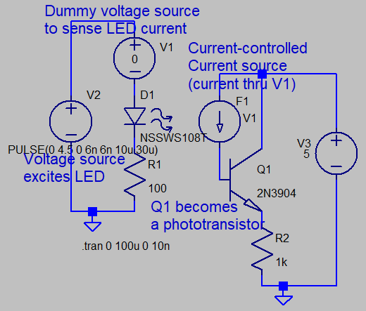
Yes, there are many 2-wire phototransistors with unconnected base. In SPICE, you might provide a base current that is remotely-proportional to the current in a LED.
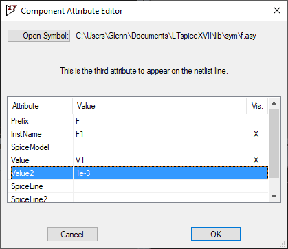
A current-controlled current source (F) is useful to provide this remote current transfer. In this schematic, V1 is a dummy voltage source of zero-volts. Current flowing through this source is transferred to F1 via a simple linear factor of 1e-3. This current flows into transistor base, simulating photocurrent. Transistor current gain boosts this via \$H_{fe}\$...in this case, about 150 times. A LED current of 14mA provides about 4.1 mA emitter current in Q1.
This would correspond to a photo-coupler current transfer ratio of about 0.3.
The parameters of F1 can be changed by right-clickingsetting up parameters for current transfer of F1:
current transfer from LED to phototransistor SPICE schematic

\$\endgroup\$
3
  • \$\begingroup\$ WHat SNR can you tolerate at say 10 kHz? \$\endgroup\$
    – D.A.S.
    Commented Nov 1, 2021 at 18:44
  • \$\begingroup\$ I haven't been asked about the signal to noise ratio tolerance, so I would assume any fair amount in this case. I've been asked to demonstrate the working of the Schmitt trigger using this noisy sensor setup. So, I would have to first actually check that it's working, before moving on to other adjustments. My primary concern is my LED not turning on right now. \$\endgroup\$ Commented Nov 1, 2021 at 18:48
  • \$\begingroup\$ Try 2:1 SNR with 10kHz noise \$\endgroup\$
    – D.A.S.
    Commented Nov 1, 2021 at 19:22
1
\$\begingroup\$

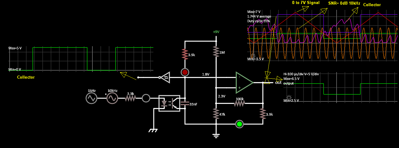
You need a high impedance current source for the hysteresis to work with impedance ratios, so use common emitter, collector out to Vin- with a Cap to filter out the noise above 1kHz.

The problems are from lack of stated assumptions and expectations.

Given was:

Vin is a square-wave with 0-7V peak to peak voltage 1kHz, some phototransistor and an OP07 with the challenge to reject unspecified "noise"

What I would have given, would be datasheets of parts to choose from and a better Rail to Rail CMOS Op Amp or a CMOS Schmitt trigger with 33% hysteresis.

Problems:

  1. OP07 drops 2~3V from each rail which is a wide tolerance that affects the accuracy of the hysteresis.
  2. The phototransistors (PT) "might" have a linear hFE of 150 but only 10~15% of this as a switch ( like ALL transistors) so the CTR after LED coupling efficiency, is much lower than what hFE implies. (need specs)

Photodiodes (PD) do not have this tolerance problem and have a CTR of >0.2 min and are very reliable , but you need a higher impedance out of the collector to amplify the voltage. Speed is not an issue here.
3. Since saturated Voh, Vol vary with the OP07 the positive feedback ratios or thresholds also vary. Sometimes they are asymmetrical. A CMOS Schmitt trigger is rail-to-rail like CMOS output OpAmps which work far better but no way to vary of %H.

You can either use emitter output for lower impedance or collector out for a nonlinear on/off or current pump. But the hysteresis needs to be independent of the PT signal non-linear impedance variations or you may get discrepancies.

  1. The last problem is noise, unless you know what it is, assume a worst case of SNR = 1 or 0dB with noise all above the signal.
    You can compute the RC filter characteristics for a LPF around 1~2kHz. If you are just sending a 1kHz clock, the phase shift won't matter, unlike with data.

When you start testing with a triangle instead of a square wave you get to adjust the input current to see the output duty cycle and thus effective CTR. It's harder to balance but easier to fix.

LED currents are often used at 5mA or as recommended so for an IR Vf=1.2V from 7V we get 5.8V/If=R or around 1kohm.

Let's see what I got. There's a dozen ways to do this. This is just one or two.

enter image description here

\$\endgroup\$
2
  • \$\begingroup\$ Ok, I'm trying this configuration out. Thanks. Any suggestion for the LED? \$\endgroup\$ Commented Nov 1, 2021 at 18:50
  • \$\begingroup\$ what does the datasheet suggest? 5mA? \$\endgroup\$
    – D.A.S.
    Commented Nov 1, 2021 at 20:04

Your Answer

By clicking “Post Your Answer”, you agree to our terms of service and acknowledge you have read our privacy policy.

Not the answer you're looking for? Browse other questions tagged or ask your own question.