3
\$\begingroup\$

I have a question about LM393 when using it as a window comparator. I know it's an open collector. The output is often paired with a pull-up resistor and an NPN. But there are circuits that use the LM393 with a PNP without a pull-up resistor. I like to connect a PNP transistor to the output of the LM393 window comparator, but do I need the pull-up resistor using the PNP? If not, I need to understand why not?

I have a supply input of 24 V and I would like to use the PNP transistor to drive an LED with Vf = 3.3 V at 25 mA.

\$\endgroup\$
3
  • 1
    \$\begingroup\$ LM393 can typically sink 16 mA. If the only thing you need to do is drive LED, you do not need a transistor. Use pull-up resistor and put diode from comparator output to GND. When the comparator output pulls the output line low, diode is off and vice-versa. \$\endgroup\$ Commented Nov 2, 2021 at 7:08
  • \$\begingroup\$ please help me for this question electronics.stackexchange.com/questions/725936/… \$\endgroup\$
    – HFAR
    Commented Sep 22 at 16:57
  • \$\begingroup\$ electronics.stackexchange.com/questions/725936/… \$\endgroup\$
    – HFAR
    Commented Sep 22 at 16:58

2 Answers 2

3
\$\begingroup\$

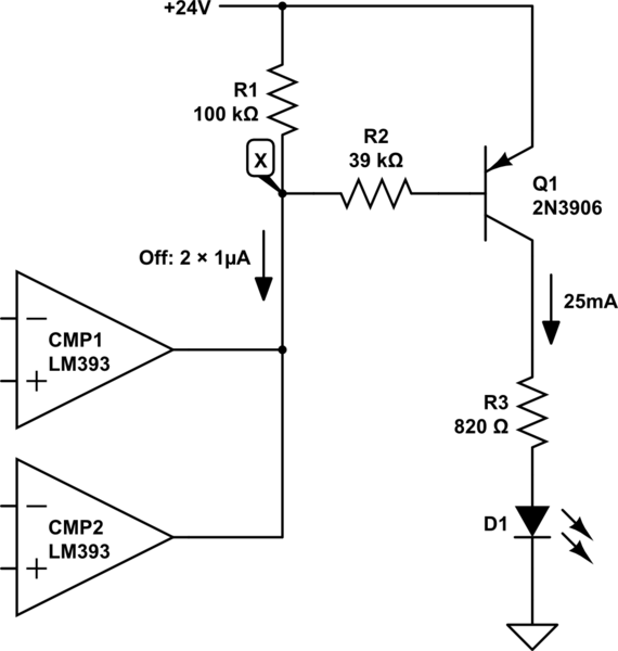
For a window comparator, I assume you have a couple of LM393 devices with their outputs connected together for wire-OR:
schematic

simulate this circuit – Schematic created using CircuitLab

In section 6.8 of the LM393 datasheet you are told that the leakage current through its output transistor could be as high as 1μA, so with a pair of them paralleled, that could be up to 2μA when they're both off (output high).

From page 2 of the 2N3906 datasheet, the current gain β is always at least 60 for collector currents up to 50mA, and is probably much more than this. For a base current of 2μA you can expect a collector current of way over \$60 \times 2\mu A = 120\mu A\$, which is easily enough to get that LED glowing quite brightly, even though it should be off.

To prevent leakage current from causing this, you must include R1, whose purpose is to prevent the potential at node X from ever dropping low enough to bias the transistor on when those 2μA leakage current are flowing. I decided arbitrarily that when 2μA is flowing through R1, 0.2V across it would be sufficiently far from 0.7V for this purpose:

$$ R_1 = \frac{V}{I} = \frac{0.2V}{2\mu A} = 100k\Omega $$

If your power supply was only 5V, leakage current sunk by the comparator outputs would be negligible, at 0.1nA (surprisingly, see the LM393 datasheet, section 6.7). In that case R1 would not be necessary, since there would be no appreciable current sunk to ground via R2. Base current would be zero, and so would collector current, in principle. In practice R1 is included to divert real-life leakage current sunk by the comparator outputs, so that it never passes via R2 to become base current.

The value for R2 is chosen to pass enough current to saturate the transistor when collector current is 25mA. Since we already know \$\beta\ge 60\$, I wanted a little head-room, so I'll assume a worst case of \$\beta =50\$. This means I need a base current of:

$$ I_B = \frac{I_C}{\beta} = \frac{25mA}{50} = 500\mu A$$

Base potential will be about 0.7V lower than 24V when a comparator output pulls node X low, so the voltage across R2 in that state will be \$V_{R2} = 24-0.7 = 23.3V\$. To pass 500μA:

$$ R_2 = \frac{V_{R2}}{I_B} = \frac{23V}{500\mu A} = 46k\Omega $$

That's an upper limit, since we need at least 500μA for \$I_B\$. The next E12 resistor value under 47kΩ is 39kΩ.

\$\endgroup\$
2
  • \$\begingroup\$ Thank you for your explanation. I completely understand why a pull-up resistor is needed and not so much when the supply voltage is low enough like 5V where the leakage current would be negligible. \$\endgroup\$
    – Citi
    Commented Nov 2, 2021 at 16:29
  • \$\begingroup\$ @Citi Leakage current from collector to emitter in the LM393 output transistor is 0.1nA when its \$V_{CE} < 5V\$. In that case, technically no pullup reisstor is needed. When \$V_{CE}=30V\$, or in your case \$V_{CE}=24V\$, leakage rises to 1µA, enough to switch Q1 on to some extent. R1 simply diverts that 1µA away from the base. \$\endgroup\$ Commented Nov 2, 2021 at 17:21
4
\$\begingroup\$

schematic

simulate this circuit – Schematic created using CircuitLab

I assume this is your configuration. Biasing must be checked, I eyeballed some plausible values but I'm not sure it would work

The pullup resistor (R1) in a PNP transistor is not strictly necessary (with a MOSFET it is), since the BJT works with current being pulled through it. When it is not pulled down there is no base current and the transistor shuts off.

However it's good practice to put it because

  1. it's cheap

  2. it gives you a slighly better switch action (not really an issue with 25mA load)

  3. it makes the circuit more resistant to disturbances

I'm kinda more worried on the drop resistor for going from 24V to 3.3V at 5mA (820 ohm with more than 500mW dissipation). Keep in mind that usually the Vf is nominal and greatly varies.

\$\endgroup\$
1
  • \$\begingroup\$ Thank you, yes I agree about the drop resistor. I do plan to connect at least 3 more LEDs in series, but yes I still would need a resistor with at least 500mW \$\endgroup\$
    – Citi
    Commented Nov 2, 2021 at 16:33

Your Answer

By clicking “Post Your Answer”, you agree to our terms of service and acknowledge you have read our privacy policy.

Not the answer you're looking for? Browse other questions tagged or ask your own question.