0
\$\begingroup\$

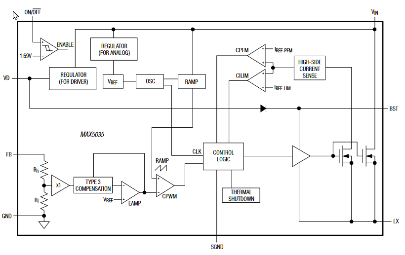
I am designing a circuit with the MAX5035. On page 11 of the datasheet I came across the following:

Use a Schottky rectifier with forward-voltage drop (VFB) less than 0.45V at +25 °C and maximum load current to avoid forward biasing of the internal body diode (LX to ground). Internal body diode conduction may cause excessive junction temperature rise and thermal shutdown. Use Table 1 to choose the proper rectifier at different input voltages and output current.

enter image description here

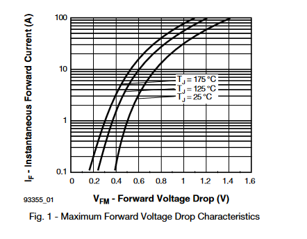
Looking at the block diagram this makes sense, but when I tried to find a diode that satisfies this Vf < 0.45 V condition I couldn't find any, at least none rated > 76V. The diode (50SQ100) recommended in Table 1 has a Vf of >0.5V at 1A and ca 0.6V at the peak switch current limit (2.5A).

enter image description here

Can I just consider this as more of a recommendation instead of a hard limit?

\$\endgroup\$
1
  • 1
    \$\begingroup\$ The MAX5035 Evaluation Kit used International Rectifier or Vishay 50SQ080 (80V, 5A Schottky diode in ancient through-hole DO-204AR package) as the freewheeling diode (this was back in 2007). These diodes are now obsolete, but a search on mouser.com for other Schottky 80V 5A diodes leads to a couple of modern equivalents (Littelfuse DST580S, Microchip HSM580Je3/TR13, Micro Commercial Components SK58L-TP, and an end-of-life through-hole OnSemi/Fairchild SB580). \$\endgroup\$
    – MarkU
    Commented Dec 30, 2021 at 1:27

2 Answers 2

0
\$\begingroup\$

A diode is absolutely required for this IC to function. The VF of the diode is perhaps not so strictly required; a well-designed IC should not have strict requirements on this parameter (it should not have large uncontrolled diodes on the LX node).

It is strange that the suggested diode doesn't meet the suggested performance. The effect you would notice is that at higher currents efficiency would decrease noticeably. You might be able to characterize this yourself by:

a) Apply power (VIN, VD), but disable the IC. The LX node will be high impedance.

b) extract a current equal to your maximum load from the LX pin (the voltage will be negative -- you can do this with a lab power supply connected 'backwards' (+ to GND, - to LX)); set the power supply V to about 1 V, and use the current limit to adjust the current.

c) Measure how much the VIN and VD currents increase as you increase the (negative) load on LX. You can calculate the impact of this on efficiency and decide if it is acceptable.

\$\endgroup\$
0
\$\begingroup\$

You left out the first part of the paragraph that you quoted:

The MAX5035 requires an external Schottky rectifier as a freewheeling diode. Connect this rectifier close to the device using short leads and short PC board traces.

The diode is not optional. The datasheet has suggestions for part numbers. I'm not sure what voltage rating you desire; the specified maximum value for \$V_{IN}\$ is 76 V

\$\endgroup\$
1
  • \$\begingroup\$ Maybe I phrased my question badly. Im absolutely aware that the freewheling diode is not optional. My problem is that no diode with the required specs exists. \$\endgroup\$
    – derklaus
    Commented Dec 29, 2021 at 20:10

Your Answer

By clicking “Post Your Answer”, you agree to our terms of service and acknowledge you have read our privacy policy.

Not the answer you're looking for? Browse other questions tagged or ask your own question.