5
\$\begingroup\$

I'm trying to implement a constant current solenoid driver (it's more of a constant wattage pwm driver, current changes with supply voltage which is fine) using UC3843 PWM driver. I'm using the automotive variant of UC3843, NCV3843 which claims to be operational upto +125'C. Here is my schematic, enter image description here
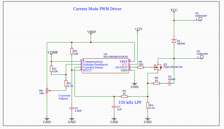
Here I use error amplifier as an inverting amplifier with gain of -2.12 to keep Comp(pin 1) voltage at about 1.67V which determines the PWM duty cycle with respect to Current sense (pin 3) feedback voltage. This feedback voltage is filtered by a RC low pass filter (R2 and C7) having cutoff frequency of 159kHz. The PWM frequency is 50kHz which determined by R5 and C1.

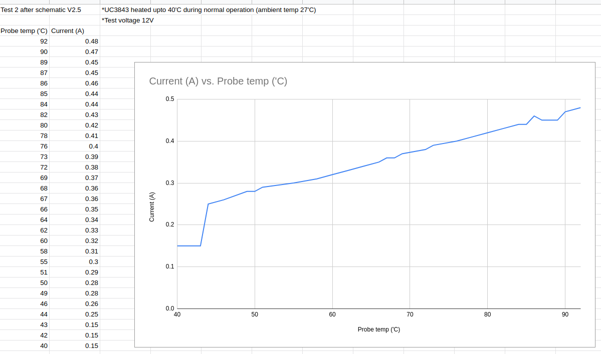
The RMS current through solenoid remains constant (0.2A) with steady supply voltage of 12V. However when I change the ambient temperature of the circuit the duty cycle increases and current rises more than 0.45A at temperature of 90'C. Here is a temperature test I did,the behavior looks mostly linear. enter image description here
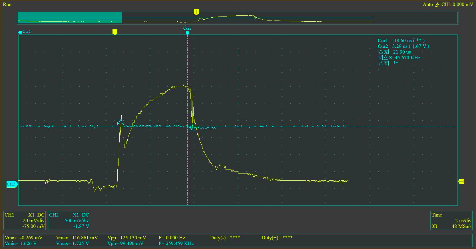
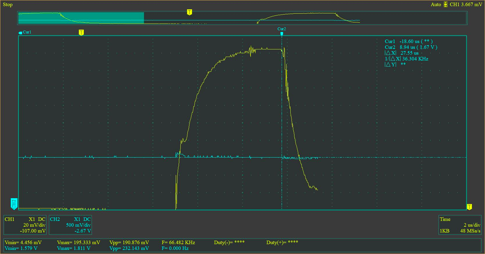
Since comp pin (pin 1) voltage determines the cutoff point of pwm signal, I have observed if it changes with temperature. However it did not change by any significant amount (around 10mV) with temperature. Here are two oscilloscope readings of comp voltage (blue) and waveform of current sense pin(pin3, yellow).

25'C enter image description here

100'C enter image description here

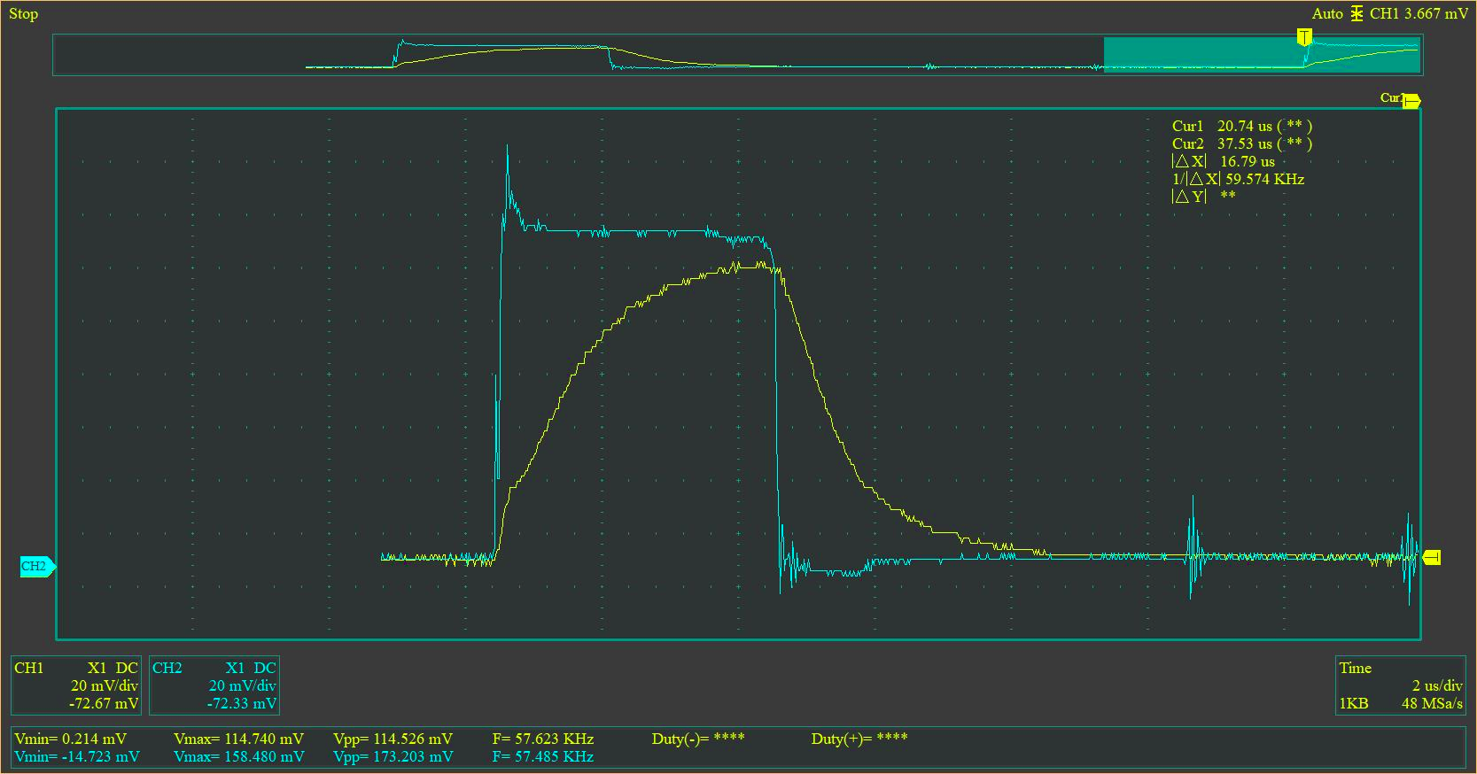
Here are the wave forms before low pass filtering(Blue) and after low pass filter (yellow) of current sensing resistor.

enter image description here

What could be the reason for current variation with temperature? Are there any design flaws with my schematic?

Note that I have built this on a well designed PCB, Not on a prototyping breadboard.

\$\endgroup\$
5
  • 1
    \$\begingroup\$ How much does the DC resistance of your solenoid change with temperature? How does the circuit perform with a fixed and stable load resistor? Do some more tests. \$\endgroup\$
    – Andy aka
    Commented Jan 9, 2022 at 9:15
  • 1
    \$\begingroup\$ Even if it works like that, I would ground the FB pin and drive the CMP directly with the pot-meter. The controller features a 1-mA output capability and is designed to be driven that way in some cases. That way, you should avoid op-amp dc drift. Make sure the reference imposed by the pot is stable though. Also, keep in mind that you have two \$V_f\$ in series from the op-amp output to the CS setpoint and these are not temperature compensated. \$\endgroup\$ Commented Jan 9, 2022 at 9:15
  • 1
    \$\begingroup\$ @VerbalKint Yes! That was the issue. I totally forget that the diodes are not temperature compensated. The TI datasheet I was referring had no description about that. However while searching about the temperature compensation I found an onsemi datasheet which has described this problem with a solution. I have grounded FB and connected CMP to voltage divider through 2 diodes in series. The issue has vanished since. Thank you very much! \$\endgroup\$
    – Anuradha
    Commented Jan 9, 2022 at 14:08
  • 1
    \$\begingroup\$ @VerbalKint If you could add your comment as an answer I can accept it. The solution by onsemi available at onsemi.com/pdf/datasheet/uc3842a-d.pdf in Figure 23. \$\endgroup\$
    – Anuradha
    Commented Jan 9, 2022 at 14:10
  • 1
    \$\begingroup\$ @Andyaka Thanks for your concern, I have found the issue with above comment. \$\endgroup\$
    – Anuradha
    Commented Jan 9, 2022 at 14:11

1 Answer 1

7
\$\begingroup\$

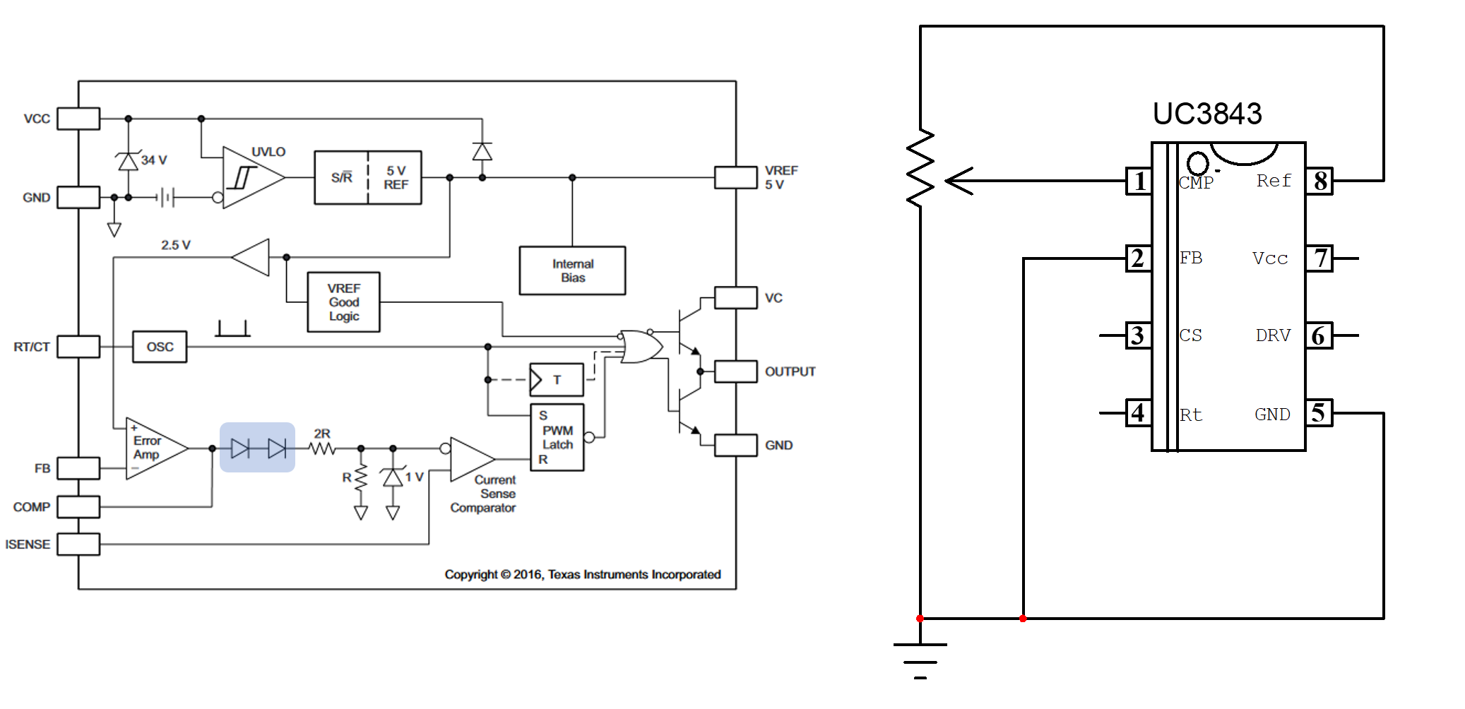
The UC384x sets the peak current setpoint by dividing the output of the internal op-amp by three. This is the role of the 2R-R network highlighted in blue in the below picture. To force a true 0-V setpoint on the current-sense (CS) comparator when needed, the designers have included two series diodes which permanently subtract 1.2 V from the op-amp output. Therefore, when operated in light- or no-load condition, the converter loop will try to impose the smallest possible peak current setpoint on the CS input. Considering the 1.2-V offset subtraction from the diodes, when the op-amp output passes below 1.2 V, there is a true 0-V applied at the CS comparator and the part operates at a zero duty ratio. That way, you don't need to optimize the op-amp negative swing.

enter image description here

This is very useful if you connect an optocoupler directly to the CMP output (in pull-down mode) and even if the saturation voltage is 0.5 V in no-load conditions, the UC384x will gladly skip cycles. Please note that these diodes are not compensated in temperature while the 1/3 ratio is.

The internal 1-mA maximum output current of the op-amp is precisely thought for this pull-down function. In your application, it would be advantageous to make the internal op-amp silent and directly fix the peak current setpoint via a bias applied at the CMP pin directly.

\$\endgroup\$

Your Answer

By clicking “Post Your Answer”, you agree to our terms of service and acknowledge you have read our privacy policy.

Not the answer you're looking for? Browse other questions tagged or ask your own question.