0
\$\begingroup\$

I have designed a BUCK converter circuit using UC3843. Here is the DATASHEET FIG1.
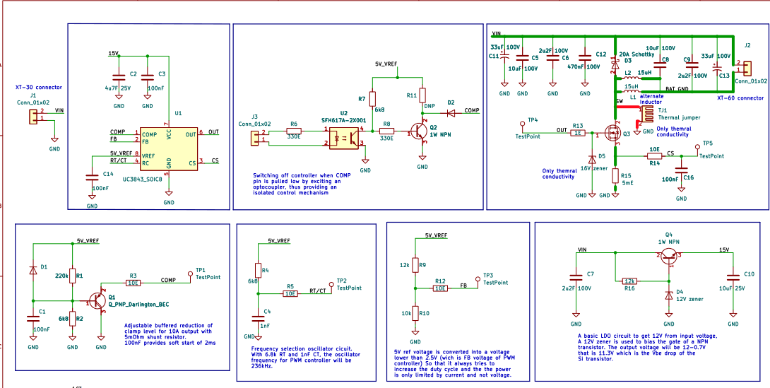
You can find the circuit diagram above. I want to limit the current to 10A and accordingly I have designed the external compensation circuit.

But, If I probe the Output pin of the IC, I am not getting any PWM output. So I started debugging and removed R3 to not have compensation in the circuit to just basically check the functionality of the IC as a PWM controller. But still there was nothing at the output pin.

I have testpoints for all the IC pins on the PCB. SO, I wanted to check the voltage on RC pin on the IC and as soon as I touch only one probe of multimeter with the Test point, the PWM output was being generated. If I am guessing correctly, my multimeter probe is adding some parasitic component to the RC pin which is making it generate PWM signal at OUTPUT pi of IC.

Can you tell me why I am experiencing this behaviour with this IC and how to fix it?

\$\endgroup\$
4
  • 1
    \$\begingroup\$ Why is the schematic so fragmented? This isn't a good (or pleasant) way of presenting a schematic because it requires excessive use of net-names to determine various conductive paths. A poor schematic that doesn't present well IMHO. \$\endgroup\$
    – Andy aka
    Commented Jan 10, 2023 at 12:55
  • \$\begingroup\$ What point did you probe that made it generate PWM? What did the PWM look like, do you mean it did something at all, or did it operate properly? How is the circuit grounded, is it floating, earthed, offline--? Do you have an oscilloscope? \$\endgroup\$ Commented Jan 10, 2023 at 13:33
  • 1
    \$\begingroup\$ With your multimeter probe you basically add some capacitance. Try to bypass R5 and increase C4 for a test. \$\endgroup\$
    – Jens
    Commented Jan 10, 2023 at 15:54
  • 1
    \$\begingroup\$ Show oscillogram of COMP, FB, RT/CT and CS. \$\endgroup\$
    – winny
    Commented Jan 10, 2023 at 20:58

1 Answer 1

4
\$\begingroup\$

... I wanted to chack the voltage on RC pin on the IC and as soon as I touch only one probe of multimeter with the Test point, the PWM output was being generated.

Check if the components are "well" soldered.

To work, some conditions for UC3843 must be met.
To test your board, don't forget shorting pin 3 & 4 of U2 (or provide something at U2 input J3).

Here is a simulation for basic wiring.

Just check waveforms (Vct always present).

enter image description here

\$\endgroup\$
4
  • \$\begingroup\$ Thanks for the reply. I found out that there was a soldering issue. The resistors R4 and R5 were swapped because of which there was a problem in generating PWM signal. But I have fixed that issue and now it works correctly as expected without load. I have designed the circuit to have a current limit of 10A. But when I connect a load (A battery in this case. 4S lithium Phosphate battery which can draw more than 10A in CC charging mode), the output current is being limited to 2.3A at an input Voltage of 60V and a battery charging Voltage of 13V. DO you know why this might be happening? \$\endgroup\$ Commented Jan 12, 2023 at 5:22
  • \$\begingroup\$ I have also probed the Gate of the mosfet and the Current sense pin also. But I am not getting expected waveform for Current sense pin. I have attached the images with the comment. drive.google.com/file/d/1-Iq0NotJoee9vjU5h37evXzn8n5-X2nN/… drive.google.com/file/d/1BQDi8bD-i2poMiinQBsoFgb1Fw7mzb4C/… I have got 4 boards assembled. And this behavior is consistent across all the boards. Note: Yellow - Gate of the MOSFET. Blue - Current sense PIN of IC in the attached oscilloscope screenshot. \$\endgroup\$ Commented Jan 12, 2023 at 5:37
  • \$\begingroup\$ R13 should be higher (? perhaps 10 -> 100 Ohm, for slowing a little the rise time current through R15). Try first with a current load lower ... 1 A, load of 12 Ohm). Try also with an input voltage lower (24 V). Remember also that a voltage (or measurement current pulses) greater than 0.5 V at the sense input "suppresses" output pulses. \$\endgroup\$
    – Antonio51
    Commented Jan 12, 2023 at 8:57
  • \$\begingroup\$ NB : R14 or C16 should be higher (time constant of some 10's microseconds, actually 1 us). \$\endgroup\$
    – Antonio51
    Commented Jan 12, 2023 at 9:05

Your Answer

By clicking “Post Your Answer”, you agree to our terms of service and acknowledge you have read our privacy policy.

Not the answer you're looking for? Browse other questions tagged or ask your own question.