1
\$\begingroup\$

I was building a distortion circuit using op-amps and had to figure out a way to power the op-amp using a single supply, in other words I wanted to obtain +half supply voltage and -half supply voltage so that I could send the (low voltage) alternated input directly to the op-amp input.

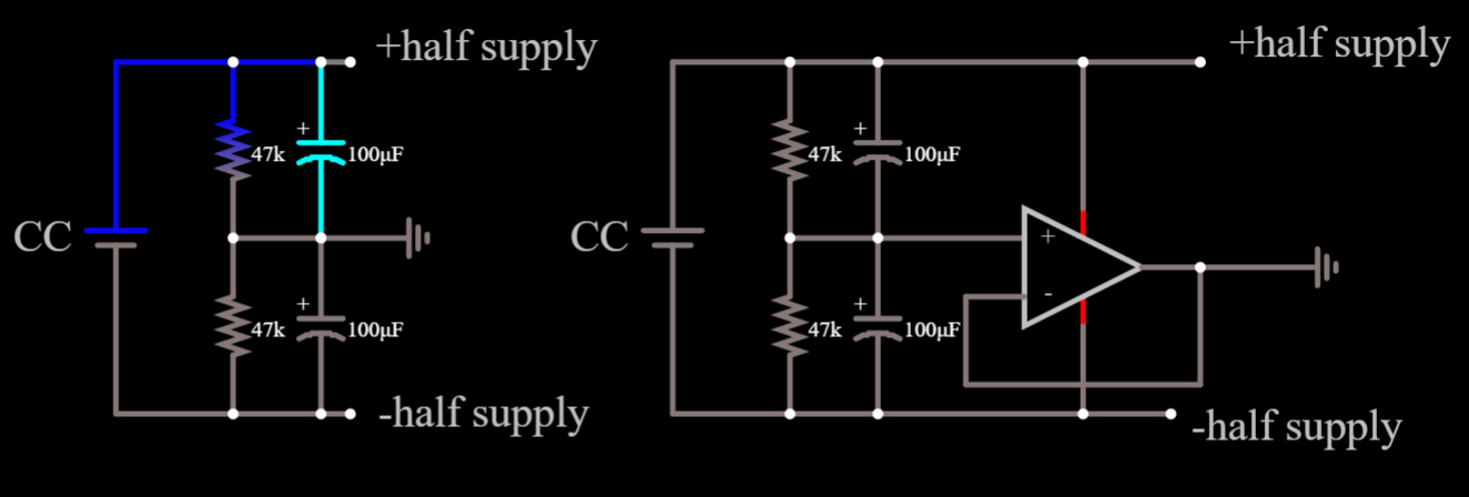
Now, the details of the circuit aren't important, since my question is only about the power stage: I came accross someone trying to build a similar circuit and he was doing the same thing as me for the power stage, the one on the left of the image.

In my case, this worked just fine, I even tested it and it worked they way it should've, instead for the guy whose question I've read this seemed to be the problem, as his circuit didn't work. Someone suggested that he'd modify his power stage as the schematic on the right, using a voltage follower in it. Seems this solved his problem.

But I don't understand, why? How does the voltage follower stabilize ground? And how in the first place is the ground not stable in the configuration on the left?

Also, as a side question, he'd suggest to have not too high resistances making up the voltage divider (I, and the guy too, originally used 1MOhm resistances) in order to "recover from asimmetries faster". I guess this has to do with charging of the capacitors, am I right? Lower resistances, lower R*C and thus any disturbance gets back to steady-state faster.

Thank you in advance for your helpenter image description here

\$\endgroup\$

2 Answers 2

1
\$\begingroup\$

But I don't understand, why? How does the voltage follower stabilize ground? And how in the first place is the ground not stable in the configuration on the left?

It's quite simple. The circuit on the left cannot sustain DC currents more than a few hundred microamps for a few seconds before a significant error is introduced in the "middle" DC value. Whereas, with the op-amp buffered circuit, the potential divider loading is just the input impedance of the op-amp (giga Ω usually) and any load current is sourced by or sunk into the op-amp. No potential dividers will be harmed!

Also, as a side question, he'd suggest to have not too high resistances making up the voltage divider (I, and the guy too, originally used 1MOhm resistances) in order to "recover from asimmetries faster". I guess this has to do with charging of the capacitors, am I right?

You might be right; 1 MΩ and 100 μF has a charge time constant (C x R) of 100 seconds so, it'll take maybe a couple of minutes for the mid-rail voltage to stabilize should there be a significant draw of DC current on it.

Whereas, 10 kΩ and 100 μF might stabilize in a couple of seconds.

\$\endgroup\$
2
  • \$\begingroup\$ Thank you, but I fear I still haven't understood completely. Count that as preparation I'm a physicist not an engineer, and I also fear my course, although general by name, was really very theoretical, or at the very least not practical. The error in the middle value is introduced because of the current that starts flowing in the ground node? \$\endgroup\$ Commented Jan 14, 2022 at 10:56
  • \$\begingroup\$ There is an error when any current is taken from the centre-point of the two resistors. That error may be small or it may be significant. The capacitors try to stabilize the voltage at the centre-point but they cannot sustain that effort for very long @Operatore_Nabla \$\endgroup\$
    – Andy aka
    Commented Jan 14, 2022 at 11:53
1
\$\begingroup\$

By splitting the supply like that you are creating a virtual ground. Note that your (audio?) input signal would have to be referenced to this virtual ground as well for your amplifier to work. If the signal is referenced to the ground of the power supply (CC) then it is still out of range for the amplifier.

The circuit on the left is stable like you pointed out, it is just not regulated. By using just resistors to set a voltage, any current that is being sunk our sourced by (for example) amplifiers or other analog circuitry connected to this virtual ground is going to shift it's potential. 47Kohms is a very high value. Even 1mA of current is going to throw off this virtual ground completely. The 100uF capacitors can only mitigate this problem for a short while. Perhaps the application that other guy build was sinking/sourcing more current from the virtual ground then yours, making it not stable while yours was.

The circuit on the right 'stabilizes' because it actually regulates the potential of the virtual ground point. The desired potential is set using the resistors. The amplifier then takes feedback from it's output (virtual ground), compares it to the potential set by the voltage devider, and will direct current from its negative and positive supply to the virtual ground in order to steer it towards the correct potential.

The benefit would be that the regulated circuit is going to consume less current. In order to keep changes to the left circuit to a minimum, the current that is running trough the divider must be much larger than the current that would be sunk or sourced from the middle of the divider. Rule of thumb is like 10x as high.

Also, if you go with the opamp approach you dont need 100uF capacitors. 1uF would work fine as well, depending on how hard you want to filter it. The opamp input will draw uA of current, so that will be fine.

\$\endgroup\$

Your Answer

By clicking “Post Your Answer”, you agree to our terms of service and acknowledge you have read our privacy policy.

Not the answer you're looking for? Browse other questions tagged or ask your own question.