0
\$\begingroup\$

I'm using a tm4c123g tiva launchpad, but I believe these questions are general.

  1. If a pin is set to output, what does it mean to "apply a different voltage on it"? This is followed by reading the post: What happens if a voltage is applied to an output MCU pin?

Does that mean using a second power source on the same breadboard?

  1. If I output a pin as GPIO high to drive an LED, why do I still need to connect the 3.3v to breadboard + rail? Shouldn't the pin itself provides enough current? This is followed by reading this schematic:

https://users.ece.utexas.edu/~valvano/Volume1/E-Book/C8_SwitchLEDv2_files/Fig8_7.jpg

  1. The datasheet doesn't go over the circuits of pins in detail. What exactly are pins? I'm asking this question in the context that they are pretty much black boxes to me and I don't know which should be avoided to damage them in a circuit.
\$\endgroup\$
1
  • 2
    \$\begingroup\$ Nicholas - Hi, (a) Re: your question 2, it may help readers to see this web page on which your linked image appears. That web page adds extra context e.g. your image "Figure 8.7" is a physical realization of schematic "Figure 8.6b" on that page. Therefore I suggest you ask any questions about the schematic, not that image. (b) Chapters 3, 4 & 6 of that e-book are also helpful. \$\endgroup\$
    – SamGibson
    Commented Feb 20, 2022 at 15:23

3 Answers 3

3
\$\begingroup\$

I'll attempt a short answer. I'm not sure I understand what you really want or need. But perhaps.

  1. Kevin just meant that when a pin is driving as an output, you do NOT want another driver also attached to the same node or wire. There should only be one driver at a time. The rest should all be receivers (or nothing at all.) This particularly applies when a the single driver uses active-high and active-low driving. (A common case.)

    That isn't a strict rule because some I/O pins can be arranged to be active-high but inactive-low, or else active-low but inactive-high. The active-low but inactive-high case is often called either open-collector or open-drain. In these cases, multiple drivers can share the same node or wire. This was a very common case many decades ago but has fallen out of favor as their are better options now.

    There is also a type of output that is called tri-state, which is slightly different than either of the above descriptions.

    As you can see, there isn't a "one size fits all" answer for this.

  2. There's no real schematic at the link you provided. And certainly no way I can see a second power source there. So I'm guessing you are asking about whether or not you need to provide an external power supply to the breadboard shown. That depends. Some I/O pins have sufficient current compliance to safely drive an LED. Some don't. If not, you very well may want an external power supply provided by the breadboard so that a circuit added to it has access.

  3. Some datasheets provide a fair amount of information about their pins. These are usually what is called "behavioral", which just means that it isn't a fully detailed schematic at the individual part level but is more a concept diagram that gets the essential details across (if you are savvy enough.)

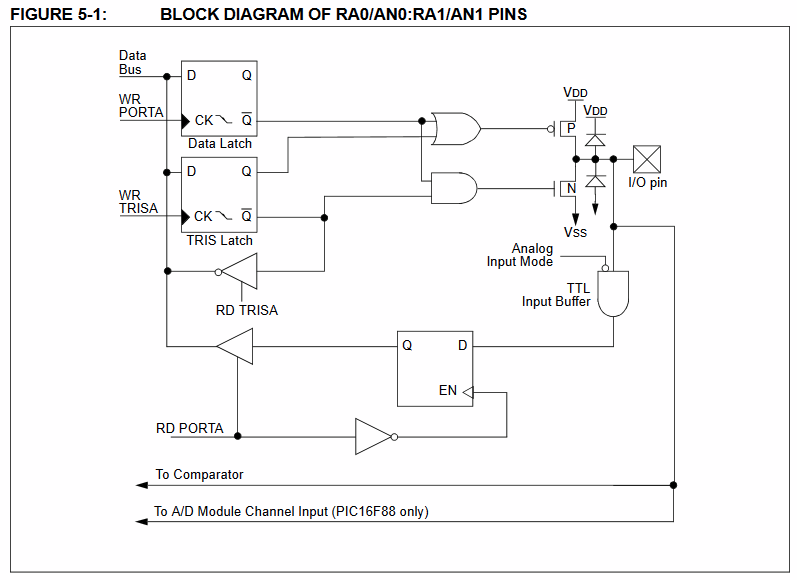
    For example, here is a pin description for the PIC16F87. You can see the I/O pin protection diodes (near the pin) and also the active high and active low drivers (the "P" and the "N" FETs near the diodes.) You also see D flip flops used to control them. And you see a lot more, besides.

enter image description here

\$\endgroup\$
2
\$\begingroup\$

When you configure an MCU pin as an output, you're telling the MCU to either connect it to the power rail (+3.3V in this case) or ground (0V), making a "high" or "low" voltage output.

If an MCU pin is configured to output high, and you try to connect it to ground, you're shorting +3.3V to ground. If an MCU pin is configured to output low, and you try to connect it to +3.3V, or 5V, or some other voltage source, you're shorting that voltage source to ground through the MCU.

Another situation you might run into is if the MCU pin is configured to output high, and you try to connect it to some non-zero voltage that is not equal to the MCU's IO voltage. In such a scenario, you're shorting the supplies together. Since the voltages don't match, a potential difference forms through the MCU with very low resistance, causing a large current to flow through the MCU and potentially damage it.

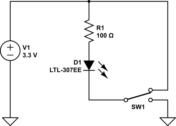
The circuit you showed for point 2 works by using the MCU pin as a sink rather than a source. Think of the pin as a switch that connects between +3.3V and 0V, like this:
schematic

simulate this circuit – Schematic created using CircuitLab

A current flows between two points in a circuit when there is a potential difference (i.e. a difference in voltage) between those points. When the switch is high, the cathode (bottom side) of the LED is at the same voltage as the top pin of the resistor, so the voltage across the LED is zero and no current flows through it. When the switch is low, the voltage at the cathode becomes 0V, so the potential difference through the resistor and LED becomes 3.3V, and a current flows, lighting up the LED.

In reality, the MCU uses a pair of transistors as a gate driver, rather than an actual switch.

\$\endgroup\$
2
\$\begingroup\$
  1. Look closely. That 3.3V wire isn't connected to the LED. It's connected to the 3.3V pin on the PCB, and from what we can see in the photo that ends up connecting to nothing else on the breadboard. It's a dead end.

If that 3.3V is an output, then the PCB is supposed to be plugged into the power supply directly and that connection on the breadboard is there for convenience if a 3.3V was required on the breadboard.

If that 3.3V is an input then the breadboard is supposed to be connected to a 3.3V power supply which has not been shown and the PCB gets its power that way.

\$\endgroup\$
1
  • \$\begingroup\$ Thanks, yeah that's where the confusion comes from. I thought that 3.3V provides certain usage in the schematic. \$\endgroup\$ Commented Feb 20, 2022 at 15:33

Your Answer

By clicking “Post Your Answer”, you agree to our terms of service and acknowledge you have read our privacy policy.

Not the answer you're looking for? Browse other questions tagged or ask your own question.