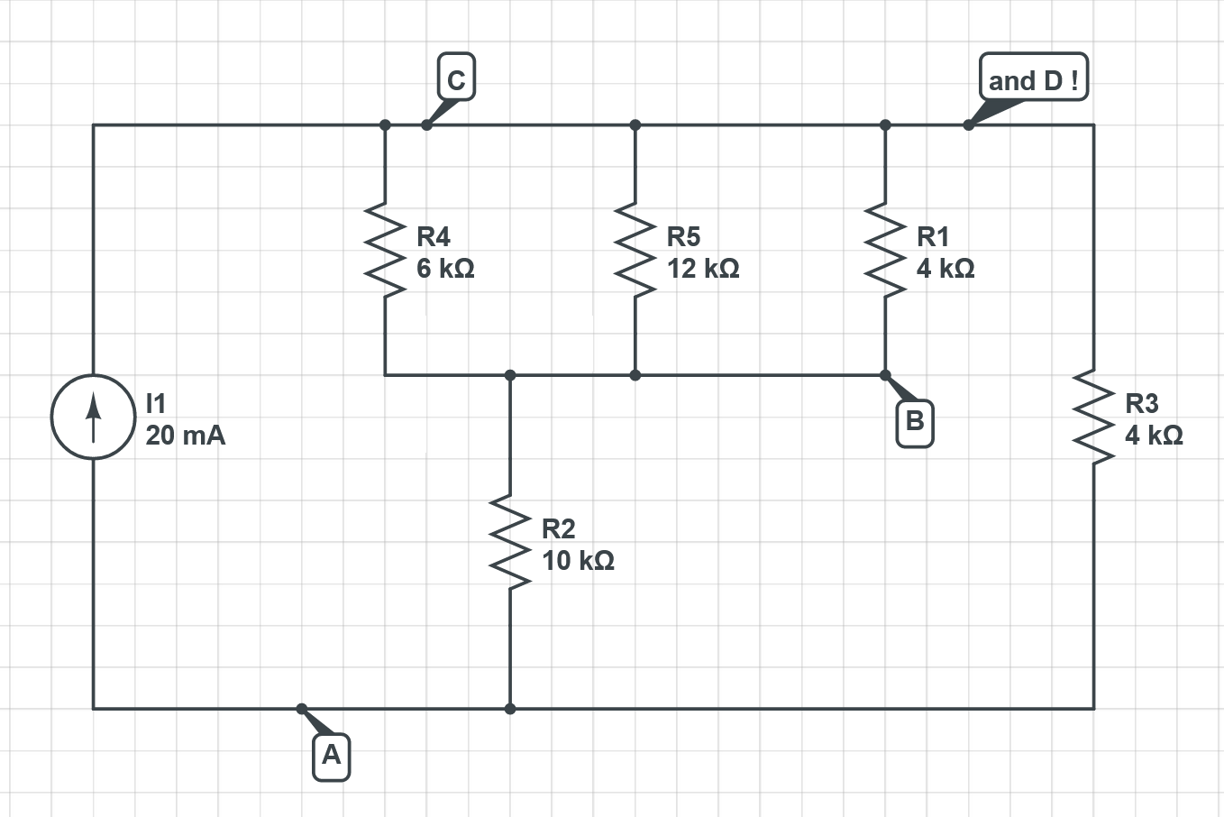
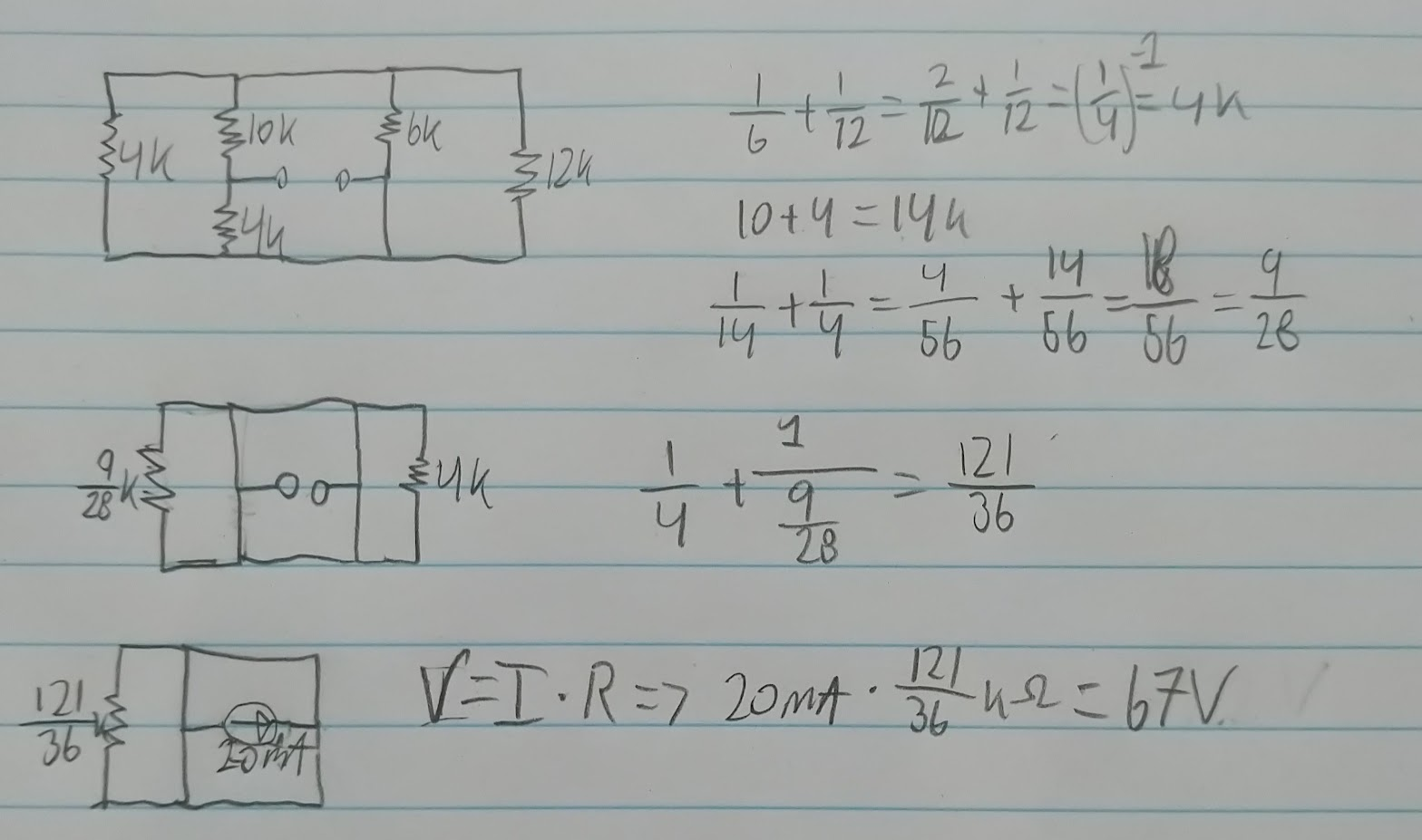
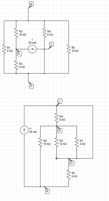
At the moment, you have a network of devices, with a random node drawn at the top, and another random node drawn at the bottom, with the current source hanging across the middle. It's drawn to confuse.
Letter all the nodes, so you don't drop any in the redrawing.
First put in your current source, and draw a bus line across the top, and the bottom, like this. I've started by putting in the 6k resistor.
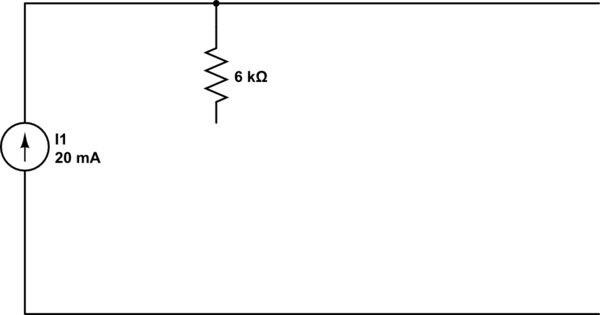
simulate this circuit – Schematic created using CircuitLab
Now draw in all the remaining components. You should find it pretty much solves itself, just for being redrawn.
Often a circuit that looks complicated is much tidier from a different view.
The whole point of a schematic is that it tells a story. The shape of the story that engineers like to see is positive at the top, negative at the bottom, current flowing down the page.
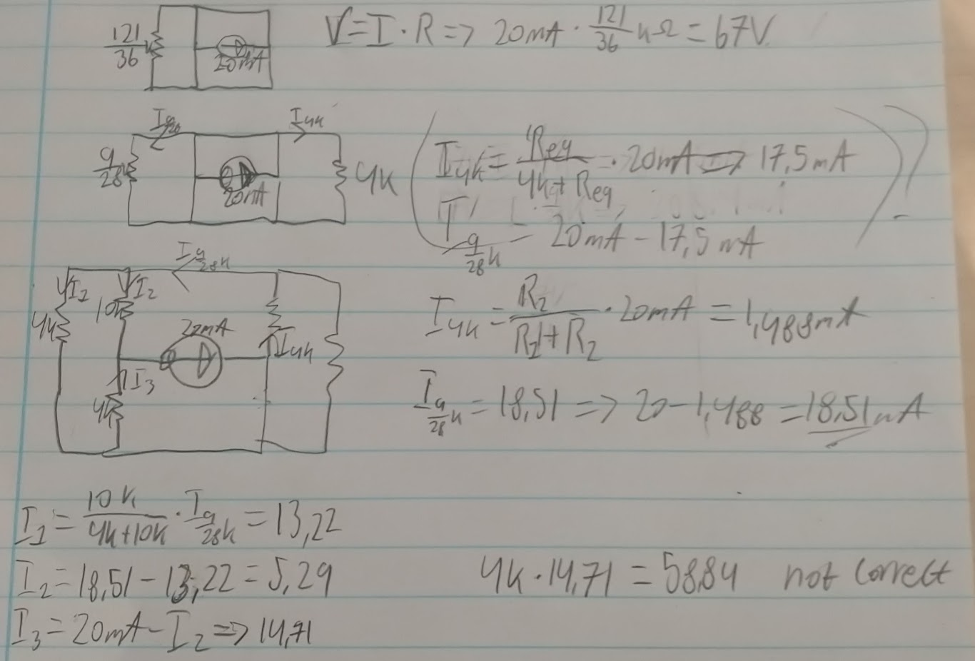
Edit following the OP's good attempt
I apologise for not having mentioned reference designators at the outset of my answer, especially as two of the resistors have the same value. Fortunately the OP was smart enough to put them in to his schematics.
Redrawing the OP's redrawing. C and D are the same node, so we need to move the D line up to C, and flip R1 and R5 round. Now it's clearly obvious which resistors are to be grouped and how they should be grouped.
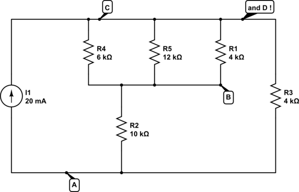
simulate this circuit
The benefit of 'positive at the top, negative at the bottom' is most shown when we make the natural extension to 'decreasing voltage down the page', and 'equipotientals across the page'. It naturally places resistors that should be paralleled in parallel, and similarly for series.
On reflection, there is a more systematic way to do this redrawing. Starting with the original drawing, identify the nodes by colouring them in, like this. Remember a node is not just a dot, it's also a line or wire between dots. All of the node is at the same voltage. If you're going into a paper-based exam, I would strongly recommend taking in some old technology like coloured pencils.
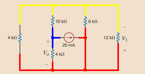
It's apparent now that there are only three nodes, and two of them belong to the current source, leaving just one additional node at an intermediate potential. It's also very easy to compare the original and redrawn circuits for equivalence. C and D are red, A is blue, B is yellow.
 From @Niel_UK
