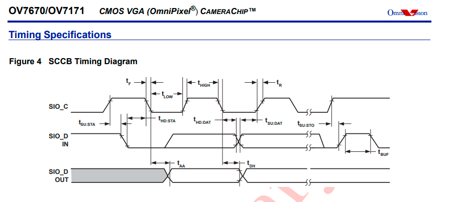
I'm looking for a SCCB library for the camera OV7670 and I have been looking everywere for C code that fits OV7670. But the problem is that my SIO_D (Data line) is always 1 when I read the data line.
This type of question is a very common question about the communication problem many SCCB users facing. So my questions are:
- Why are my code only reading the data line as active high?
- Do you know a good working easy to use SCCB library that works?
Codes that I found useful:
https://gist.github.com/muhammadyaseen/75490348a4644dcbc70f https://github.com/ctc8631/ov7670/blob/master/src/OV7670.c#L338
Datasheet for OV7670: http://www.voti.nl/docs/OV7670.pdf
User manual for OV7670: http://www.haoyuelectronics.com/Attachment/OV7670%20+%20AL422B%28FIFO%29%20Camera%20Module%28V2.0%29/OV7670%20Implementation%20Guide%20%28V1.0%29.pdf
My Code:
#define INPUT false
#define OUTPUT true
#define WRITE_ADDRESS 0x42
#define READ_ADDRESS 0x43
#define SIO_CLOCK_DELAY 1

static void delayMicroseconds(uint16_t ms){
    HAL_Delay(ms); // TODO: Fixa så det blir ms
}

static void DirSCCB(bool output){
    GPIO_InitTypeDef GPIO_InitStructure;
    GPIO_InitStructure.Pin =  SIO_D_Pin;
    GPIO_InitStructure.Pull = GPIO_PULLUP;
    GPIO_InitStructure.Speed = GPIO_SPEED_LOW;
    GPIO_InitStructure.Mode = output == false ? GPIO_MODE_INPUT : GPIO_MODE_OUTPUT_PP;
    HAL_GPIO_Init(SIO_D_GPIO_Port, &GPIO_InitStructure);
}

static void StartSCCB() {
    DirSCCB(OUTPUT);
    delayMicroseconds(SIO_CLOCK_DELAY);

    HAL_GPIO_WritePin(SIO_D_GPIO_Port, SIO_D_Pin, GPIO_PIN_SET);
    delayMicroseconds(SIO_CLOCK_DELAY);

    HAL_GPIO_WritePin(SIO_C_GPIO_Port, SIO_C_Pin, GPIO_PIN_SET);
    delayMicroseconds(SIO_CLOCK_DELAY);

    HAL_GPIO_WritePin(SIO_D_GPIO_Port, SIO_D_Pin, GPIO_PIN_RESET);
    delayMicroseconds(SIO_CLOCK_DELAY);

    HAL_GPIO_WritePin(SIO_C_GPIO_Port, SIO_C_Pin, GPIO_PIN_RESET);
    delayMicroseconds(SIO_CLOCK_DELAY);
}

static void StopSCCB() {
    HAL_GPIO_WritePin(SIO_D_GPIO_Port, SIO_D_Pin, GPIO_PIN_RESET);
    delayMicroseconds(SIO_CLOCK_DELAY);

    HAL_GPIO_WritePin(SIO_C_GPIO_Port, SIO_C_Pin, GPIO_PIN_SET);
    delayMicroseconds(SIO_CLOCK_DELAY);

    HAL_GPIO_WritePin(SIO_D_GPIO_Port, SIO_D_Pin, GPIO_PIN_SET);
    delayMicroseconds(SIO_CLOCK_DELAY);
}

void NoAckSSCB(){

    HAL_GPIO_WritePin(SIO_D_GPIO_Port, SIO_D_Pin, GPIO_PIN_SET);
    delayMicroseconds(SIO_CLOCK_DELAY);

    HAL_GPIO_WritePin(SIO_C_GPIO_Port, SIO_C_Pin, GPIO_PIN_SET);
    delayMicroseconds(SIO_CLOCK_DELAY);

    HAL_GPIO_WritePin(SIO_C_GPIO_Port, SIO_C_Pin, GPIO_PIN_RESET);
    delayMicroseconds(SIO_CLOCK_DELAY);

    HAL_GPIO_WritePin(SIO_D_GPIO_Port, SIO_D_Pin, GPIO_PIN_RESET);
    delayMicroseconds(SIO_CLOCK_DELAY);
}

static bool SCCBWrite(uint8_t m_data){
    uint8_t j;
    bool success;

    //Loop transmit data 8 times
    for (j = 0; j < 8; j++){
        if((m_data << j) & 0x80 )
            HAL_GPIO_WritePin(SIO_D_GPIO_Port, SIO_D_Pin, GPIO_PIN_SET);
        else
            HAL_GPIO_WritePin(SIO_D_GPIO_Port, SIO_D_Pin, GPIO_PIN_RESET);

        delayMicroseconds(SIO_CLOCK_DELAY);

        HAL_GPIO_WritePin(SIO_C_GPIO_Port, SIO_C_Pin, GPIO_PIN_SET);
        delayMicroseconds(SIO_CLOCK_DELAY);

        HAL_GPIO_WritePin(SIO_C_GPIO_Port, SIO_C_Pin, GPIO_PIN_RESET);
        delayMicroseconds(SIO_CLOCK_DELAY);
    }

    HAL_GPIO_WritePin(SIO_D_GPIO_Port, SIO_D_Pin, GPIO_PIN_RESET);
    delayMicroseconds(SIO_CLOCK_DELAY);

    // Change to input
    DirSCCB(INPUT);
    delayMicroseconds(SIO_CLOCK_DELAY);

    HAL_GPIO_WritePin(SIO_C_GPIO_Port, SIO_C_Pin, GPIO_PIN_SET);
    delayMicroseconds(SIO_CLOCK_DELAY);

    if(HAL_GPIO_ReadPin(SIO_D_GPIO_Port, SIO_D_Pin) == GPIO_PIN_SET)
        success = false;
    else
        success = true;

    HAL_GPIO_WritePin(SIO_C_GPIO_Port, SIO_C_Pin, GPIO_PIN_RESET);
    delayMicroseconds(SIO_CLOCK_DELAY);

    // Change to output
    DirSCCB(OUTPUT);
    delayMicroseconds(SIO_CLOCK_DELAY);

    return success;
}

static uint8_t SCCBRead(){
    // Prepare
    uint8_t data = 0;
    DirSCCB(INPUT);
    delayMicroseconds(SIO_CLOCK_DELAY);

    // Loop
    for(uint8_t i = 8; i > 0; i--){
        delayMicroseconds(SIO_CLOCK_DELAY);
        HAL_GPIO_WritePin(SIO_C_GPIO_Port, SIO_C_Pin, GPIO_PIN_SET);
        delayMicroseconds(SIO_CLOCK_DELAY);
        data = data << 1;
        if(HAL_GPIO_ReadPin(SIO_D_GPIO_Port, SIO_D_Pin))
            data++;
        HAL_GPIO_WritePin(SIO_C_GPIO_Port, SIO_C_Pin, GPIO_PIN_RESET);
        delayMicroseconds(SIO_CLOCK_DELAY);
    }

    return data;
}

bool InitOV7670(){
    // Hardware reset
    HAL_GPIO_WritePin(CAMERA_RESET_GPIO_Port, CAMERA_RESET_Pin, GPIO_PIN_SET);
    delayMicroseconds(SIO_CLOCK_DELAY);
    HAL_GPIO_WritePin(CAMERA_RESET_GPIO_Port, CAMERA_RESET_Pin, GPIO_PIN_RESET);
    delayMicroseconds(SIO_CLOCK_DELAY);

    // Software reset
    if(!WriteOV7670(COM7, COM7_VALUE_RESET))
        return false;
    else
        return true;
}


bool WriteOV7670(uint8_t reg, uint8_t data){
    StartSCCB();
    if(!SCCBWrite(WRITE_ADDRESS)){
        StopSCCB();
        return false;
    }

    delayMicroseconds(SIO_CLOCK_DELAY);
    if(!SCCBWrite(reg)){
        StopSCCB();
        return false;
    }

    delayMicroseconds(SIO_CLOCK_DELAY);
    if(!SCCBWrite(data)){
        StopSCCB();
        return false;
    }

    StopSCCB();

    return true;
}

bool ReadOV7670(uint8_t reg, uint8_t *data){
    StartSCCB();

    if(!SCCBWrite(WRITE_ADDRESS)){
        StopSCCB();
        return false;
    }
    delayMicroseconds(SIO_CLOCK_DELAY);

    // Write data (Address of register in Camera Module)on SCCB/I2C interface
    if(!SCCBWrite(reg)){
        StopSCCB();
        return false;
    }
    delayMicroseconds(SIO_CLOCK_DELAY);

    StopSCCB();
    delayMicroseconds(SIO_CLOCK_DELAY);
    StartSCCB();

    // Write data (Address of slave device for Read) on SCCB/I2C interface
    if(!SCCBWrite(READ_ADDRESS)){
        StopSCCB();
        return false;
    }
    delayMicroseconds(SIO_CLOCK_DELAY);

    // Received data from Camera Module (SCCB/I2C)
    *data = SCCBRead();

    NoAckSSCB();

    StopSCCB();

    return true;
}

