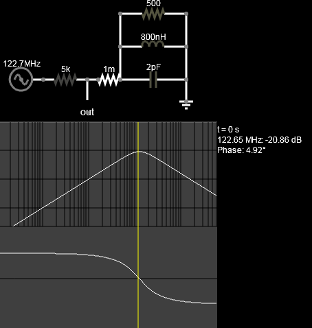
From an answer to an earlier question you asked is this circuit: -
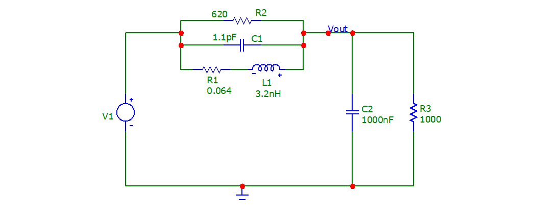
The values for R1, R2, L1 and C1 were taken from this ferrite bead table: -
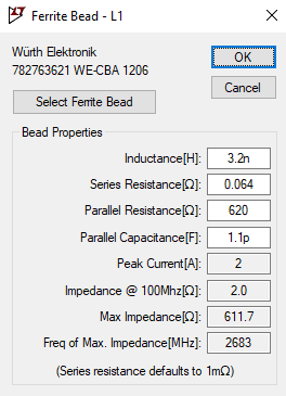
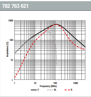
But, if all you have is the graph shown below, you can calculate L1 using XL (20 Ω) at 1 MHz and, you'll get \$L_1 = \frac{X_L}{2\pi 10^6}\$ = 3.18 μH.
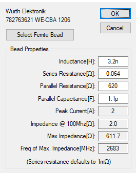
However, in your original question, you had stated (or rather LTSpice appeared to state) that L1 was 3.2 nH and that now seems a flawed value. Clearly the ferrite beads are the same part number and also, the maximum impedance does not occur at 2.683 GHz but occurs at 100 MHz.
So, something is awry with the values in that question you posed earlier. Clearly, maximum impedance occurs at around 100 MHz (not 2.683 GHz) and, I trust this graph rather than LTSpice: -
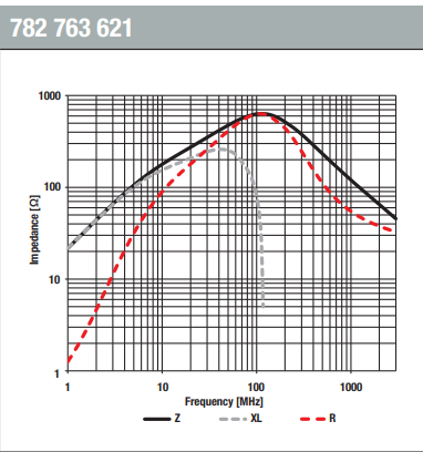
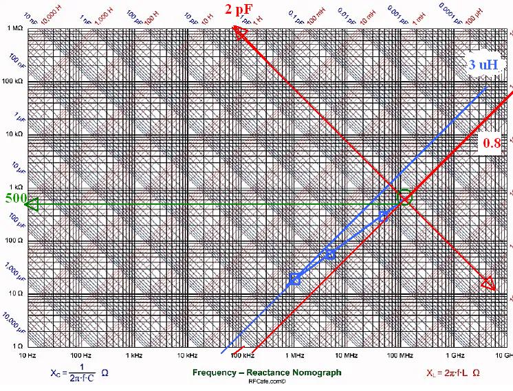
So, accepting that the inductance L1 is 3.2 μH, the capacitance can be found using the maximum impedance frequency of 100 MHz (the graph above shows that) and the value of L1: -
$$\text{100 MHz} = \dfrac{1}{2\pi\sqrt{L_1C}}$$
I get C1 = 0.792 pF.
For R2, the clue is in the part number's last three digits 621 and in the table on page 12 of the data sheet. R1 is stated as being 0.1 Ω.

