-1
\$\begingroup\$

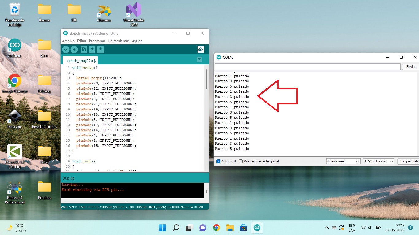
The ESP32 devkit recognizes inputs 1,3 and 5 as high state when they shouldn't

the code

void setup()
{
  Serial.begin(115200);
  pinMode(23, INPUT_PULLDOWN);
  pinMode(22, INPUT_PULLDOWN);
  pinMode(1, INPUT_PULLDOWN);
  pinMode(3, INPUT_PULLDOWN);
  pinMode(21, INPUT_PULLDOWN);
  pinMode(19, INPUT_PULLDOWN);
  pinMode(18, INPUT_PULLDOWN);
  pinMode(5, INPUT_PULLDOWN);
  pinMode(17, INPUT_PULLDOWN);
  pinMode(16, INPUT_PULLDOWN);
  pinMode(4, INPUT_PULLDOWN);
  pinMode(2, INPUT_PULLDOWN);
  pinMode(15, INPUT_PULLDOWN);
}

void loop()
{
  int puerto1 = digitalRead(23);
  if (puerto1 == HIGH)
  {
    Serial.println("Puerto 23 pulsado");
  }

  int puerto2 = digitalRead(22);
  if (puerto2 == HIGH)
  {
    Serial.println("Puerto 22 pulsado");
  }

  int puerto3 = digitalRead(1);
  if (puerto3 == HIGH)
  {
    Serial.println("Puerto 1 pulsado");
  }

  int puerto4 = digitalRead(3);
  if (puerto4 == HIGH)
  {
    Serial.println("Puerto 3 pulsado");
  }

  int puerto5 = digitalRead(21);
  if (puerto5 == HIGH)
  {
    Serial.println("Puerto 21 pulsado");
  }

  int puerto6 = digitalRead(19);
  if (puerto6 == HIGH)
  {
    Serial.println("Puerto 19 pulsado");
  }

  int puerto7 = digitalRead(18);
  if (puerto7 == HIGH)
  {
    Serial.println("Puerto 18 pulsado");
  }

  int puerto8 = digitalRead(5);
  if (puerto8 == HIGH)
  {
    Serial.println("Puerto 5 pulsado");
  }

  int puerto9 = digitalRead(17);
  if (puerto9 == HIGH)
  {
    Serial.println("Puerto 17 pulsado");
  }

  int puerto10 = digitalRead(16);
  if (puerto10 == HIGH)
  {
    Serial.println("Puerto 16 pulsado");
  }

  int puerto11 = digitalRead(4);
  if (puerto11 == HIGH)
  {
    Serial.println("Puerto 4 pulsado");
  }

  int puerto12 = digitalRead(2);
  if (puerto12 == HIGH)
  {
    Serial.println("Puerto 2 pulsado");
  }

  int puerto13 = digitalRead(15);
  if (puerto13 == HIGH)
  {
    Serial.println("Puerto 15 pulsado");
  }

  delay(100);
}

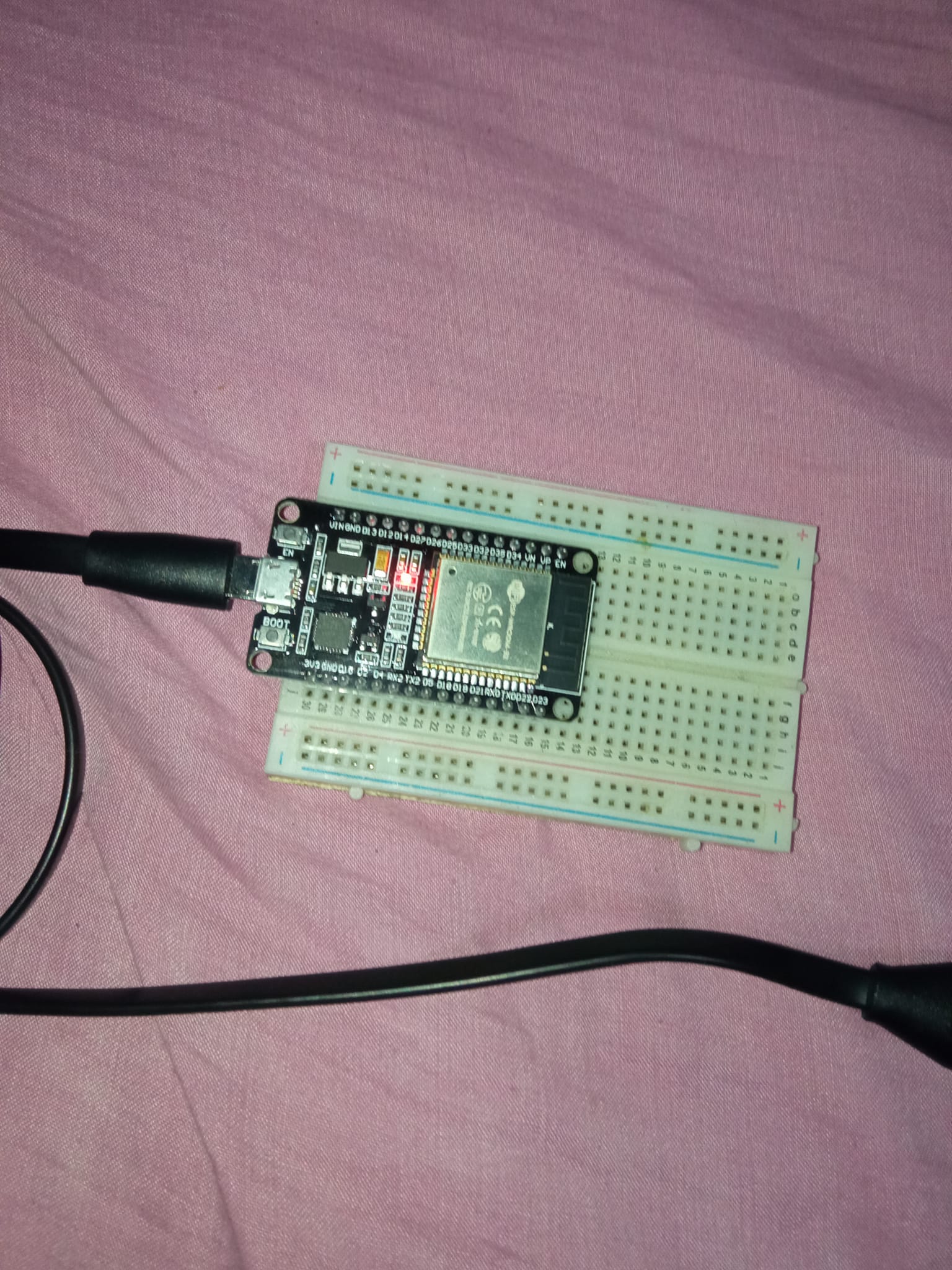
I have nothing connected enter image description here

status shows high when it should show low

enter image description here

Internal Pull-down don't work on GPIO1, GPIO3 and GPIO5 I need the pin state to show in low

\$\endgroup\$
11
  • 7
    \$\begingroup\$ Floating inputs are very susceptible to electrical noise, and are not "LOW" by default. Please see electronics.stackexchange.com/q/481378/9612 and electronics.stackexchange.com/q/437647/9612 for explanation and guidance. \$\endgroup\$
    – nanofarad
    Commented May 6, 2022 at 2:24
  • 2
    \$\begingroup\$ They almost certainly do. Your photo of the breadboard clearly shows floating CMOS inputs, and your code clearly shows no attempt to enable a pullup or pulldown resistor. Add pullup/pulldown resistors. If you still think they don't, edit your post with additional info to explain why the issue seems different than floating CMOS inputs. \$\endgroup\$
    – nanofarad
    Commented May 6, 2022 at 15:19
  • 2
    \$\begingroup\$ While you don't have the sensor connected, you need something to pull it down. If it's a digital sensor with a push-pull interface then having a reasonable pull-down or pull-up should cause it no significant problem. Also, from esp32.com/viewtopic.php?f=18&t=11349: "Note that not all GPIOs on an ESP32 have pullup and pulldown resistors." -- you may need to use physical resistors, as described in the existing link. \$\endgroup\$
    – nanofarad
    Commented May 7, 2022 at 1:49
  • 3
    \$\begingroup\$ @Diego The ESP8266 doesn't have a pull-down resistor option on most of its pins (except pin 16) esp8266.com/viewtopic.php?t=7255 , so INPUT_PULLDOWN will not actually do anything \$\endgroup\$
    – BeB00
    Commented May 8, 2022 at 3:10
  • 1
    \$\begingroup\$ @BeB00, the board on the picture is an ESP32. the esp8266 core doesn't have INPUT_PULLDOWN, it only has INPUT_PULLDOWN_16 \$\endgroup\$
    – Juraj
    Commented May 8, 2022 at 5:35

2 Answers 2

1
\$\begingroup\$

Many ESP boards have built-in resistors to pull certain IO pins high/low, as that's required for boot configuration or suchlike. The ESP micros are indeed quite annoying in this, and you have to keep this in mind when you actually want to use your GPIOs as anything; at least compared to most other microcontrollers which actually let you use your GPIOs without too many strings attached :)

Here's a website I found, showing which IO pins can be safely used for what purpose, as many aren't as general purpose as you'd wish they were. It does list GPIO 5 as one with a pull-up, but I'm not terribly sure about pins 1 and 3 - those seem to connect to the USB-UART chippo?

Do check the schematic of your development board, I'm sure you can find it somewhere :D


Just a small note about the test software you've written: Wouldn't it be slightly more readable/easier to make fewer mistakes in if you used an array of pin numbers there, and just iterated through it to test their status? Copy-pasted code is generally a pain to maintain. "Don't repeat yourself," and all that mantra.

\$\endgroup\$
0
\$\begingroup\$

If you attach 10k resistors from each pin that is giving you trouble to ground your spurious high signals will go away.

Also there’s a good chance that if you attach the sensors you intend to use to these inputs the spurious readings will go away.

This problem is caused by the high sensitivity of CMOS inputs - they will pick up stray fields and charge like you wouldn’t believe.

\$\endgroup\$

Your Answer

By clicking “Post Your Answer”, you agree to our terms of service and acknowledge you have read our privacy policy.

Not the answer you're looking for? Browse other questions tagged or ask your own question.