0
\$\begingroup\$

In this video, there are two main rows of capacitors on a Class D audio amplifier. I understand the power supplies need power filter capacitors, and that output stages need DC decoupling capacitors.

What I don't understand is why so many are used. For the smaller, blue capacitors (there are 16) why not just use e.g. 8 capacitors of double the size? or 4 of 4x the size? (I am assuming they are connecting in parallel to increase capacitance.)

Same question (essentially) for the bigger capacitors, although I might understand in this case since they are so large.

\$\endgroup\$
1
  • 2
    \$\begingroup\$ Car amplifiers are generally quite space-constrained, especially with respect to height. Also, there's also usually a strong requirement for low ESR and high ripple current capability, other things that parallel capacitors excel at. \$\endgroup\$
    – Dave Tweed
    Commented May 21, 2022 at 21:02

3 Answers 3

1
\$\begingroup\$
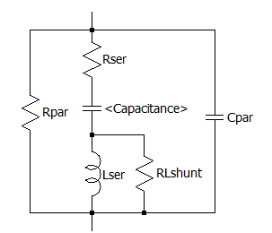
  • Polar e-caps tend to be selected for ultralow resistance, ESR to improve the attenuation of RF from the series L and DCR resistance.

The actual equivalent circuit of most caps looks like this. enter image description here
  • Keep this in mind when you only see C on the Logic Diagram.

  • Parallel caps of half the value and size in parallel makes the aspect ratio of L:W smaller which determines the inductance and raises the Self-Resonant-Frequency (SRF)

  • Although C/2 // C/2 is the same as C if they occupy the same area, the ESR is reduced in half which raises the Q and the maximum attenuation near SRF when the switching frequency is just below that.

Yet we know from physics and Saturn PCB design that the parasitic inductance is a ratio of length to width on a log scale. For SMDs mostly being 2:1 L:W ratio has a certain parasitic inductance. for the same multi-layer separation if it were 1:1 the inductance is reduced by almost 50% which raises the parallel self-resonant freq. (SRF) by almost 25%.

Thus putting more in parallel raises the bandwidth of the filter up to the SRF when designed properly.

These are common tradeoffs between cost, area, and critical attenuated required.

\$\endgroup\$
7
\$\begingroup\$

One reason is that large value capacitors tend to be taller, using multiple shorter ones allow them to fit into the same height as the rest of the circuitry.

Another reason is that capacitors have parasitic impedances, resistance and inductance. Putting those impedances in parallel reduces them. Capacitances in parallel add, resistance and inductances in parallel follow the formula $$Z_{tot} = \frac{1}{\frac{1}Z_1 + \frac{1}{Z_2} + ...+ \frac{1}{Z_n}} $$

\$\endgroup\$
1
  • 1
    \$\begingroup\$ Larger caps tend to already have lower ESR than smaller caps. But this is not the case for inductance. The larger cap has a larger form factor which might cause it to have higher inductance than a smaller cap (true for ceramics and probably true for electrolytics as well). \$\endgroup\$
    – DKNguyen
    Commented May 21, 2022 at 23:10
6
\$\begingroup\$

Capacitors are not ideal components: as a side effect of being stacked foils, they have additional inductivity and resistance that is problematic for high-frequency applications (like class D amplifiers). Increasing the size of a capacitor increases those parasitic elements, putting several capacitors in parallel decreases them.

\$\endgroup\$
1
  • \$\begingroup\$ Do take care with component routing however. Trace resistance and inductance can be a problem. \$\endgroup\$
    – TLW
    Commented May 21, 2022 at 21:37

Your Answer

By clicking “Post Your Answer”, you agree to our terms of service and acknowledge you have read our privacy policy.

Not the answer you're looking for? Browse other questions tagged or ask your own question.