0
\$\begingroup\$

I am designing a 30V 5A power supply and after simulations working fine I decided to make it on actual hardware. But during the first run, something shorted and the power supply didn't even turn on.

These are before and after photos of PCB:

Photos (facing some issue on forum, so shared google drive link)

The black area on PCB is around the bridge rectifier. The bridge rectifier is shorted and some tracks have been removed due to high current(maybe). Other area on PCB is completely fine.

This is the whole schematic of power supply if required: link

The diodes used for bridge rectifier is RL207 (Datasheet) which has 2A 1000V rating and 70A surge current rating.

The max surge current according to the simulation is supposed to be around 20A which the RL207 should be able to handle even after derating.

Can anyone help me to find the actual problem?

The reasons that I could think of but not sure:

  1. The residue flux after soldering shorted some tracks when 230VAC was connected. I had already verified all the connections using a multimeter before powering the circuit and orientation of diodes are also correct.

  2. The inrush current was too high for diodes to handle during charging of 470uF capacitor due to which rectifier shorted and therefore AC mains got shorted.

Some extra information if required:

  1. Clearance for copper pour on PCB is 1mm.
  2. RL207 diodes were taken from an old computer power supply in working condition.
  3. NTC 10D-9 thermistor was also taken from the same old computer power supply.
  4. The yellow and black wire taped together was used in place of fuse as I didn't had any at that time.
\$\endgroup\$
4
  • 4
    \$\begingroup\$ With 230VAC separated by 1 mm it would be a good idea to clean the surface well and paint it with an insulator. \$\endgroup\$
    – Perry Webb
    Commented May 24, 2022 at 17:49
  • \$\begingroup\$ It could just be the way the light reflects off the board, but a there are a lot of places where I can't tell if the solder is shorting across tracks. Have you inspected it with a magnifying glass? \$\endgroup\$ Commented May 24, 2022 at 18:18
  • \$\begingroup\$ It cannot be inspected now; those areas have turned into metal vapor deposits. \$\endgroup\$
    – rdtsc
    Commented May 24, 2022 at 18:18
  • 1
    \$\begingroup\$ Did the board go through wave solder? That seems the cause of excess solder between the traces. You could coat the board except for the through holes. \$\endgroup\$
    – Perry Webb
    Commented May 24, 2022 at 19:07

2 Answers 2

1
\$\begingroup\$

Diode D1 (1N4148) cannot handle the high reverse voltage and is of no use here anyway. It's just a short circuit after some µs.

\$\endgroup\$
3
  • \$\begingroup\$ For rectification, Diode D1 is RL207 and 4 of this diodes were used in bridge configuration as mentioned in my question and the schematic. 1n4148 has been used in auxiliary winding to power the controller IC UC3842. \$\endgroup\$
    – tinkerer
    Commented May 24, 2022 at 18:09
  • 3
    \$\begingroup\$ @tinkerer: No! In your schematic D1 is between +300V and via pin 4 and 5 (transformer winding) GND. If it is an 1N4148 it can't survive there! And the aux winding 4-5 is far from reaching 300V, so diode D1 has no function. \$\endgroup\$
    – Jens
    Commented May 24, 2022 at 18:21
  • 1
    \$\begingroup\$ Okay since schematic was not opening correctly on my phone I misread the schematic. Diode D1 is indeed 1N4148 and was there with transformer reset winding to carry power back to capacitor during reset of transformer. Due to reset winding the reverse voltage was actually double of voltage across capacitor and it definitely can't withstand that. I removed this circuit from board and checked it with multimeter and it is open both ways. So I guess this diode is the culprit. I don't how I made a blunder of choosing this diode for this purpose. Thank you so much for pointing out. \$\endgroup\$
    – tinkerer
    Commented May 25, 2022 at 2:00
3
\$\begingroup\$

The diode rating appears to be ok. But I cannot tell from the google drive schematic how these are even used, so cannot tell if the surge current would exceed 70A.

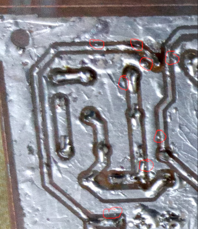
The issue is most likely contamination between the high-voltage traces. Any one or more of the following areas could be to blame:

Why it failed

Keep in mind that 240VAC = 340VDC peak-to-peak. Anything causing the tiny gap between traces to diminish could have initiated an arc with up to 340V across it. Solder blobs, flux bridges, trace being too close, mote of dust, etc.

Such areas must be exceptionally clean and free of any contaminants, including flux; flux dissolves metal slightly, so can become slightly conductive itself. Usually not a problem at 5V or 12V, but can be critical at 340V. Even those brands of flux which claim to be "no-clean" - clean it anyways. Top-side also. Lacquer thinner or Acetone cleans it well. Isopropyl alcohol also works, but is slow.

It would be better to use larger creepage and clearance distances on such high-voltage traces to lessen the chance of arc-flash.

Three additional things:

  1. I don't see a fuse. A thermistor (used as a current-limiting device) is not a fuse. Mains-powered anything must have a fuse, to prevent fire.
  2. Consider using a Variac (adjustable auto-transformer) to vary the AC voltage being supplied to this unknown supply. This allows you to test at different input voltages and maybe would have alerted to to an issue (and the Variac fuse blown) before the voltage got high enough to severely damage things.
  3. Consider powering an unknown supply from a series incandescent lamp. If the lamp bulb lights then goes out, then the supply has charged and should be working. If the bulb stays on, then the supply is shorted and damage is reduced because the full input current is dissipated by the lamp. This doesn't necessarily work for all supplies (some may actually oscillate), but it shouldn't cause damage for a quick three-second test.
\$\endgroup\$
1
  • 2
    \$\begingroup\$ The schematic only looks bad in Google's built-in viewer. If you download it and look at it it's pretty clear. \$\endgroup\$ Commented May 24, 2022 at 18:52

Your Answer

By clicking “Post Your Answer”, you agree to our terms of service and acknowledge you have read our privacy policy.

Not the answer you're looking for? Browse other questions tagged or ask your own question.