0
\$\begingroup\$

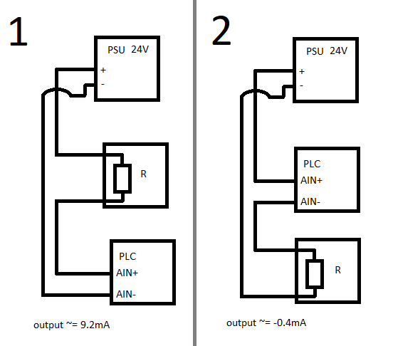
Is the order of transmitter and receiver connection in the current loop important? I have +24VDC power supply unit, PLC with current analog input and the sensor (for test case it's just 2.35kOhm resistor). If I connect it in the typical way (first diagram: PSU -> sensor -> PLC AIN) then everything works well (output = 9.2mA). But when I swap PLC AIN and the sensor (second diagram) then the output is invalid (-0.4mA)

schematic diagram of test loop

Why is that happen? Theoretically current AIN of the PLC is just another resistor (about 250Ohm) in series in the circuit so I thought both connections should work.

\$\endgroup\$
5
  • 2
    \$\begingroup\$ is the PSU fully floating, or does it share an unintended unnoticed GND connection with either of the other elements in the loop? \$\endgroup\$
    – Neil_UK
    Commented May 25, 2022 at 11:19
  • \$\begingroup\$ Is the +24V source the same that is used to power the PLC? If yes, than the 4-20mA input of your PLC is probably GND-Referenced and not floating. \$\endgroup\$
    – kruemi
    Commented May 25, 2022 at 11:35
  • 1
    \$\begingroup\$ @Neil_UK no, it's the same PSU that powers PLC, so there might be some unnoticed GND connection. If I use another, separated PSU then the measure is accurate. \$\endgroup\$
    – Maciej
    Commented May 25, 2022 at 12:41
  • \$\begingroup\$ @kruemi please see my answer to Neil_UK \$\endgroup\$
    – Maciej
    Commented May 25, 2022 at 12:42
  • \$\begingroup\$ You might have your answer there, then. I would have expected a PLC current loop input to be isolated, for just this reason, but maybe not, , maybe they expect you to use isolated power, or maybe the PLC also has a loop exciting power output that they expect you to use. \$\endgroup\$
    – Neil_UK
    Commented May 25, 2022 at 12:50

1 Answer 1

0
\$\begingroup\$

As you are using the same power supply for the PLC and the sensor there is a possibility that the negative input of the ADC for the 4-20mA interface has a connection to GND.

It might be written in the documentation of the PLC or the analogue Module you're using (but it's not always).

I know from experience that the 4-20mA input of a Siemens Logo!8 AM2 Module works even if the - of the analog in is not connected (despite no reference to that fact in the documentation).

If your analog input is not galvanically isolated (look at the datasheet/decumentation) it's probably GND referenced in some way.

\$\endgroup\$

Your Answer

By clicking “Post Your Answer”, you agree to our terms of service and acknowledge you have read our privacy policy.

Not the answer you're looking for? Browse other questions tagged or ask your own question.