I am currently working on an analog telephone project.
I have some questions.
ICs and Central are below:
- Central: KX-NS500 (gives 28VDC)
- DTMF receiver: MT8870
- DTMF generator: HT9200B
- MCU: STM32WB10CCU5
- Line Mng. IC: TEA1062AT
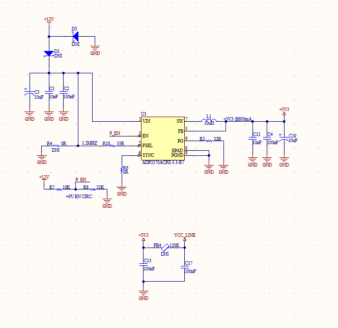
- Power IC: 3V3 fixed SMPS
Below is my circuit diagram with some details;
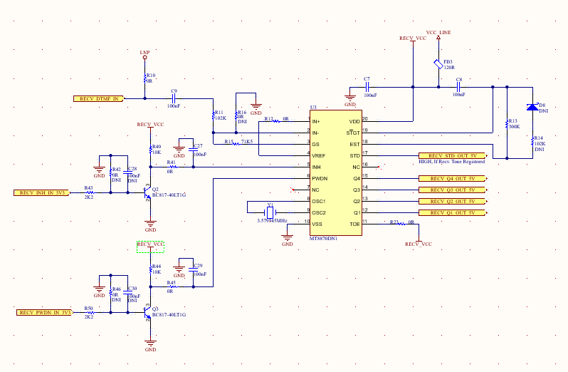
- DTMF receiver
Here is the DTMF receiver with MT8870 IC. I built the transistor circuits because the datasheet says the IC's typical Vdd = 5.0V however it works fine with 3V3.
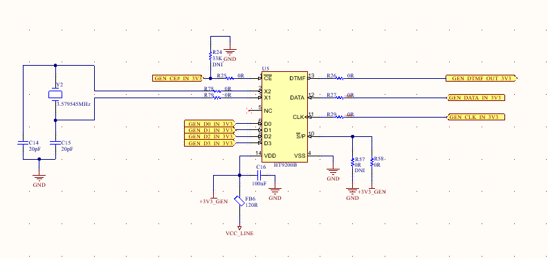
- DTMF generator
Here is the tone generator circuit. It works in parallel mode.
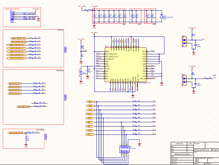
- MCU
Here is MCU circuit diagram. Some keypads and GPIOs.
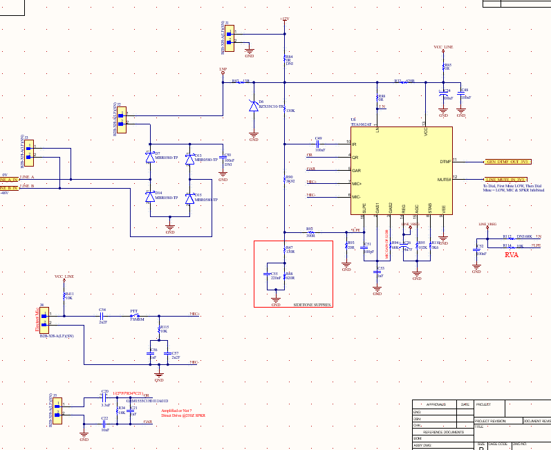
- Line (TEA1062AT)!!!
Here are the TEA1062AT and line connection. J2 stands for "Hook Switch" and J3 for "Line Input".
Here I have some problems.
First of all, when I supply all other ICs (receiver, generator, MCU) with 3V3 from the power supply (isolated from the TEA1062AT's Vcc) all of them work fine. I can send and receive DTMF tones.
When I try to supply using the TEA1062At VCC pin (the datasheet says you can use this pin to supply peripherals,) the current from this pin is not being enough.
When I upload empty code to MCU, I have stable 3.32V @VCC from TEA. (VCC_Line net) but when I try to send and receive some data from the MCU to the generator and receiver, that 3.32V oscillates. I tried to increase the current capability by lowering R114 and by increasing R93. It did not work.
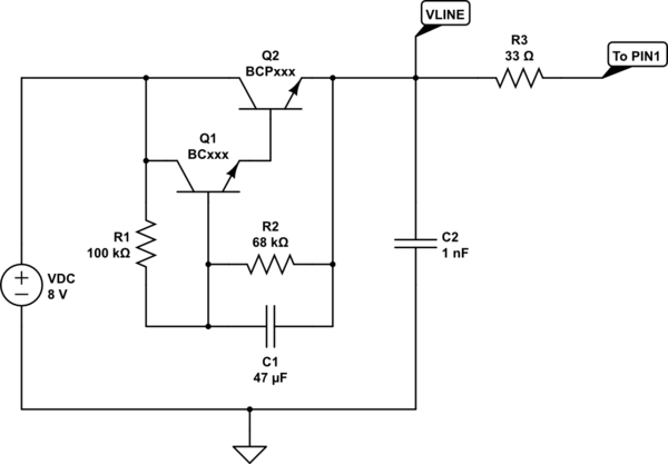
Then I tried get fixed fixed 3V3 voltage by using the circuit below:
I take supply for this circuit from after R87 (voltage drop here is approximately 9V,) It works. This time I could not get the DTMF tone from TEA1062 line pin.
Ok.
- Is there any way to supply all peripherals without/with TEA1062AT?
- How can I interface with Central - TEA1062 IC?
- What is wrong in these circuits?

