1
\$\begingroup\$

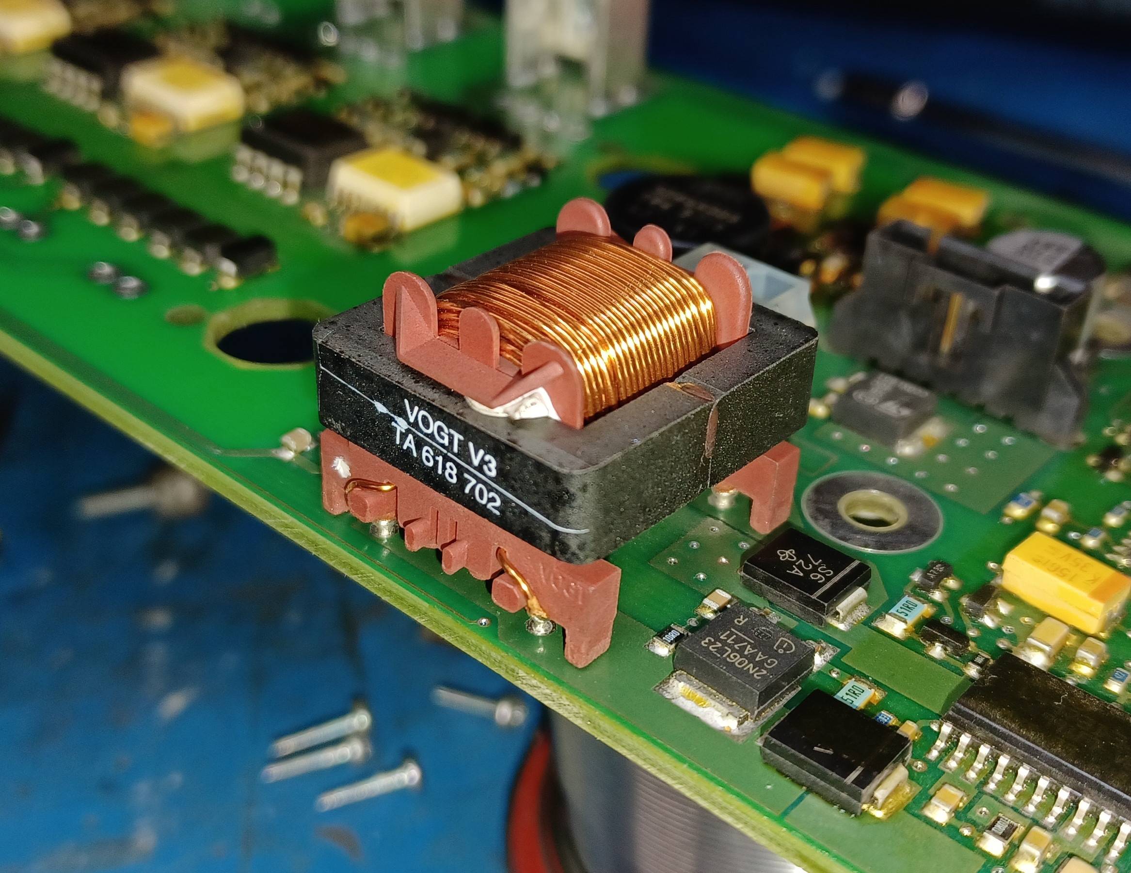
Is this a "gapped" ferrite transformer/choke?

Here, two "E" cores are bonded together with brown epoxy. There isn't any intentional, visible gap, yet there are three bond points and that must introduce some gap...

How are these considered: gap or no gap?

Edit: There is no visible gap on the outer legs - if you zoom in, the halves are very close. But "no visible" could still be 0.005mm, so right there is 0.015mm. This particular coupled inductor has not been disassembled to determine if an actual gap was cut into the center leg; lets assume all legs are equal in length.

\$\endgroup\$
2
  • 1
    \$\begingroup\$ Maybe they meant it as the gap, though it will lead to a lot of fringing. Usually the center leg is shorter, it's also easier to control the length. As it is there, it looks like a total of several mm. If the other leg has a shorter gap, it's probably bad construction (e.g. not pressed enough). \$\endgroup\$ Commented Jun 14, 2022 at 13:23
  • 3
    \$\begingroup\$ Probably not. If you need a gap, you gap the inner leg. \$\endgroup\$
    – winny
    Commented Jun 14, 2022 at 13:30

2 Answers 2

1
\$\begingroup\$

There will always be a small gap between the contact surfaces of two ferrites because of surface roughness. This processing note from TDK provides additional information:

enter image description here

So your example would probably be considered an ungapped core.

\$\endgroup\$
2
\$\begingroup\$

Impossible to tell by inspection. Given some more context (pinout, surrounding circuit), or measurements (windings and pinout, inductance, estimated number of turns), the internal gap can be estimated.

Inductivity is given by: \$A_L = \frac{\mu_0 A_e}{l_c / \mu_r + l_g}\$. It looks like it may be a 1:1 transformer with same size and length wire, and, so nice of them not to wrap it in tape so it can be seen clearly as-is -- an estimate of turns should be feasible here. Basically count layers and turns per layer, multiply, then halve for the two windings and that should be close. We can assume at first it's generic power ferrite, \$\mu_r \approx 2000\$, and measure \$A_e\$ and \$l_c\$ from the outer dimensions of the core. (The center peg will be twice the width of the side legs, and the E core is the same height all around.) \$A_e\$ is height times width of the center peg. For path length \$l_c\$, take the perimeter around one loop (center peg to one leg and back), along the midline. Roughly, the outer dimensions of the core, minus center peg width, divided by two. And \$\mu_0\$ is the inductivity of free space, about 1.257 nH/mm. (Doing everything in mm gets the result in nH/t^2, or you can use whatever system of units you like, given suitable conversion. Google Calculator handles these expressions just fine.) Finally, \$A_L\$ is in units of inductance per squared turn; multiply by the number of turns squared, to get total measured winding inductance. Or, in this case, to go backwards and solve for \$l_g\$.

\$\endgroup\$

Your Answer

By clicking “Post Your Answer”, you agree to our terms of service and acknowledge you have read our privacy policy.

Not the answer you're looking for? Browse other questions tagged or ask your own question.