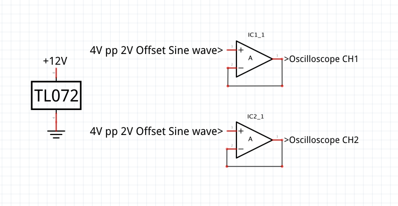
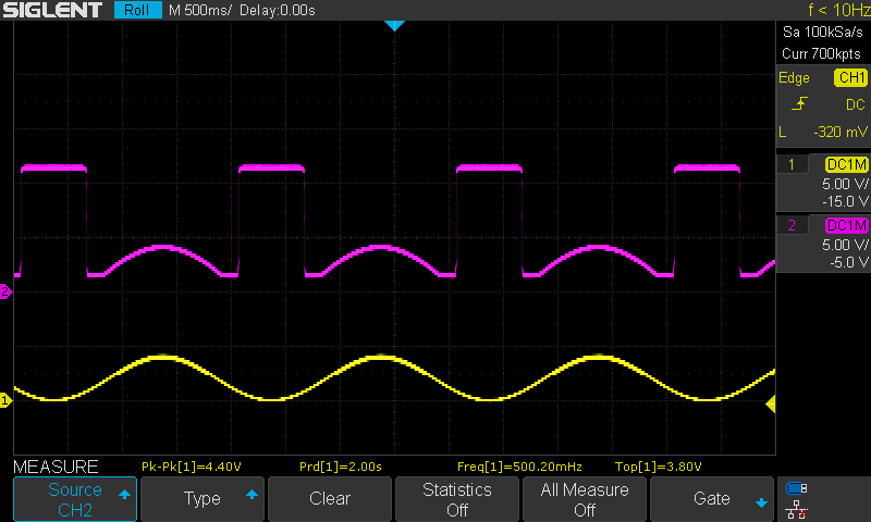
After noticing a strange behaviour from a TL072P Opamp in a circuit I was building, I decided to test my stock, coming from two different batches, side to side. I am getting confusing results when feeding them both with a 4V p/p sine wave with a 2V Offset so that everything stays in the positive. Here are the crude schematics and a screenshot of my oscilloscope. Any idea?
3 Answers
The signal you are providing at the input ranges from 0 to 4V, and falls outside the range that this particular op-amp can deal with.
In the datasheet for the TL072, under several sections entitled "Electrical Characteristics" (there are a few, for different variants of the device), there is a parameter called \$V_{ICR}\$ or \$V_{CM}\$, "Common-mode input voltage range". This tells you what range of voltages you may apply to the inputs, and in all cases that range does not extend all the way to the negative supply potential (0V in your case).
On page 19, for instance, it says the minimum input potential acceptable to the TL072C is -12V (typically), when the negative supply is -15V. That's a full 3V of unusable input range, between -15V and -12V! Terrible.
For the "H" version, on page 17, the parameter is called \$V_{CM}\$, and is specified to be no lower than \$V_{CC-}+1.5V\$.
Whatever the model, in your application, where \$V_{CC-}=0V\$, this means that the op-amp is not guaranteed to behave well if the inputs are less than +1.5V. You may get lucky, and have a device that works well all the way down to +1V or even +0.5V, but the datasheet is warning you that this is unadvisable.
There's another thing to consider, the output. That same datasheet tells you that the output isn't capable of reaching all the way to the supply potentials either! On page 19, that's parameter \$V_{OM}\$. Typically the output range of the TL07x falls 1.5V short of the supply potentials in either direction!
You've built a voltage follower, expecting it to do what the name suggests, but it will fail for two reasons. First, the input you provide is incompatible with this device, and second, even if that weren't the problem, the output isn't even capable of dropping below +1.5V.
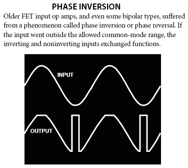
Your experiment is wonderfully educative, in that it shows you how this particular op-amp responds to inputs that fall outside the common-mode input voltage range. Clearly it deals with that condition by violently swinging its output as far positive as it can go!
-
\$\begingroup\$ Thank you. I solved my problem by connecting pin 4 to -12V instead of ground. Now I have my voltage follower working on the full 0-4V range. \$\endgroup\$– brunobhrCommented Jun 27, 2022 at 10:16
-
\$\begingroup\$ I must shamefully confess that I have mistaken a TL072 for a LM358, hence the completely different measurement. Although it doesnt invalidate your answer, do you think I should delete the question? \$\endgroup\$– brunobhrCommented Jun 27, 2022 at 17:25
-
1\$\begingroup\$ The only difference that matters is that the input voltage range and output range of the LM358 get close to the negative power supply rail. Otherwise the material is still valid and true. No need to delete, if you think the question fits the answer, and vice versa. \$\endgroup\$ Commented Jun 27, 2022 at 17:28
-
\$\begingroup\$ @brunobhr no, though you might do any appropriate correction. Mistaken in which way, are the scope traces for a TL072 or an LM358? \$\endgroup\$ Commented Jun 28, 2022 at 2:52
-
\$\begingroup\$ I wouldn't expect an LM358 to behave as shown here. Those traces are exactly what I would expect from a TL072 though. It doesn't make sense to me, to be honest. \$\endgroup\$ Commented Jun 28, 2022 at 2:58
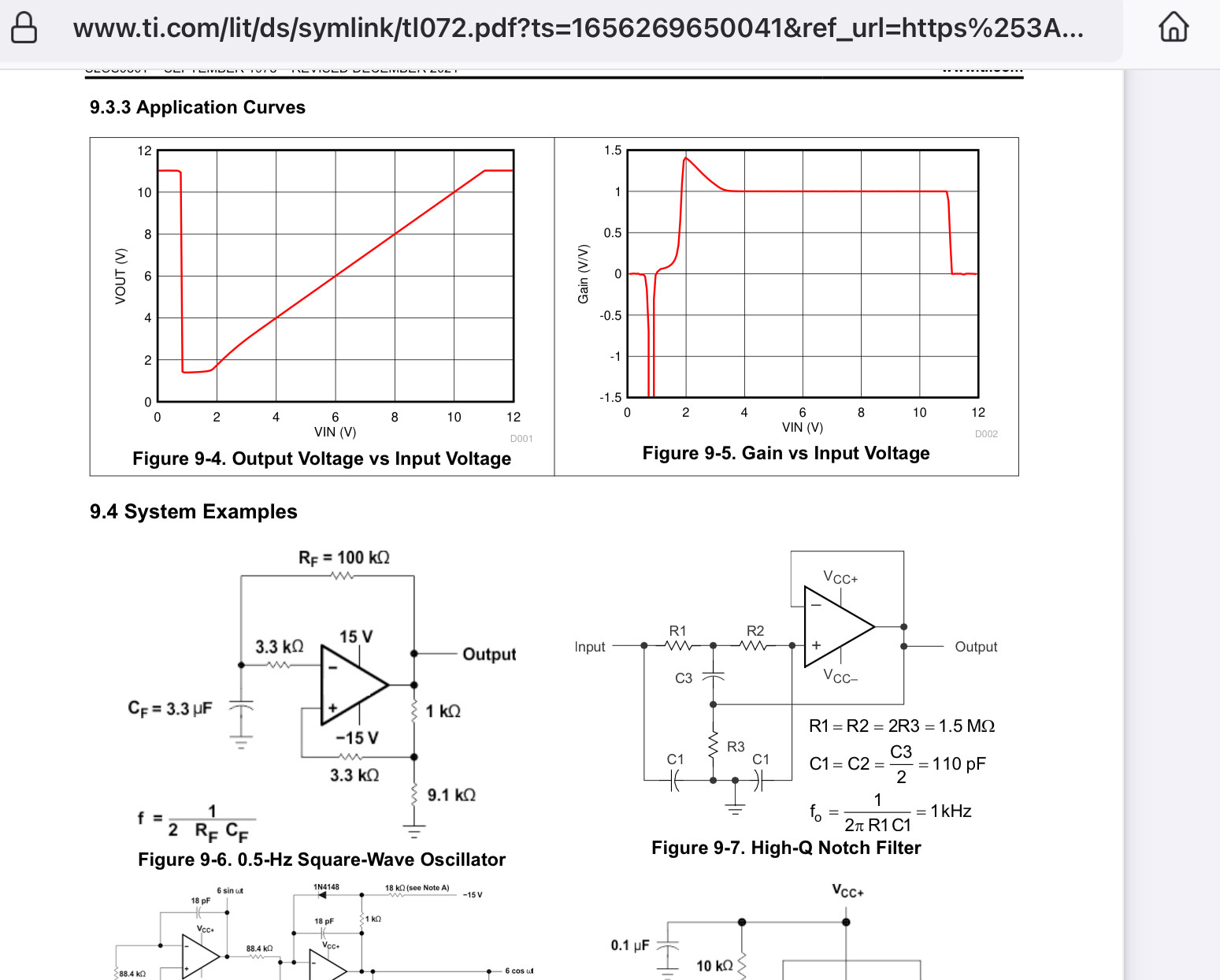
My TL072 datasheet says, "Recommended input common-mode voltage minimum (Vcc-) +4V" but yours goes all the way down to Vcc- producing "Opamp Phase Inversion". A newer version that is a TL072H says, "Recommended input common-mode voltage minimum (Vcc-) +2V". Here is a graph explaining the problem:

The importance of reading and understanding datasheets cannot be ignored.
The transfer function of the unity gain follower is clearly shown towards the end of the 94 pages.
The linear range is limited due to biasing of the JFET inputs. The gain goes down to zero then reverses at 0 and under volts.
You need to bias the input in this linear input range or use bipolar power supplies. Normally one AC couples to Vin+ and biases Vin- to Vcc/2 to use this voltage follower for a single supply.


