1
\$\begingroup\$

I've read several other previous posts about this, and none of them seem to address the exact conceptual doubt I'm having, so I'll take a shot at posting this...

Question: How can we have high voltage as well as low current?

Situation: a hydroelectric generating dam generates 13.8kV and steps it up to 138kV, so winding ratio is 1:10. Neglecting losses, by conservation of energy we have that

P_in = P_out.

Or

I_inV_in = I_outV_out, I_out = (V_in/V_out)I_in => 0.1I_in = I_out

--> So we have 10% the current but at the same power, which is great because this reduces I^2*R losses and we can therefore use cables rated at lower ampacity, saving $, materials, and energy. I get all of this, and I think I understand how transformers and generators work, but...

Here's where I get confused:

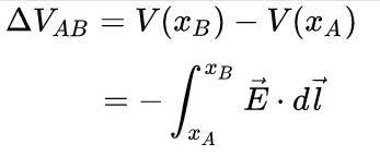
Now my understanding of voltage comes from the path-integral definition, which states that it's the work necessary to move a charge, per unit charge, along a path against a conservative electric field (very analogous to gravitational potential energy):

(1) integral path definition of voltage

And my microscopic understanding of charge carrier motion comes from the relation of drift velocity to the electric field

(2) V_d = uE,

where V_d is the average drift velocity, u is the electron mobility, and E is the electric field.

And finally my microscopic understanding of current is a function of drift velocity

(3) I = neAV_d,

(where n is electron density, e electron charge, A cross sectional area of conductor).

My confusion:

A) If we increase voltage V, we must increase electric field E, since V is proportional to E (1).

B) If we increase E, then we must increase V_d, since V_d is proportional to E (2).

C) If we increase V_d, we must increase I, since I is proportional to V_d (3).

Therefore: if we increase V, since A)--implies-->C), we must increase I.

==> So -- how can we have high voltage as well as low current, or how can we raise the voltage without raising the current?

(I must be missing something, because I know we do it, and I get how transformers exploit Faraday's law to transform voltages. Perhaps is it the load at the end of the line that has a large impedance, and this is what limits the current on the secondary? All of the residences, businesses, etc, that are drawing power? Is this one of the reason why supply must match demand?)

\$\endgroup\$
5
  • 1
    \$\begingroup\$ You are correct, if you have a 1 watt load and transformers are ideal, it will take 1A at 1V which is 1W at low voltage side, and it will also take 1W on the high voltage side which might be 0.1A at 10V. So even if it is a 1 ohm load at 1V, it is not a 1 ohm load at 10V, it is a 100 ohm load at 10V. Is this what you are after? \$\endgroup\$
    – Justme
    Commented Jul 10, 2022 at 6:56
  • \$\begingroup\$ Hmm yeah this might help me out...This seems equivalent to the technique of referring a load to the primary or secondary side in order to create an equivalent circuit. OK - so this would mean that impedance at, say, a household, would look really large from the perspective of the high-voltage line on the primary of the step-down transformer? If you have some load R_house, then R'_house = (N1/N2)^2*R_house >> R_house. So my suspicion at the end of my post is on the right track? \$\endgroup\$
    – MusedPony
    Commented Jul 10, 2022 at 7:15
  • 2
    \$\begingroup\$ E in the drift velocity equation is the electric field on one wire (end-to-end along the conductor) and not the terminal voltage between two wires. You are mixing one thing up with another. \$\endgroup\$
    – Andy aka
    Commented Jul 10, 2022 at 9:57
  • \$\begingroup\$ Are you integrating along the same thing? What relevance is the transmission line in this example, are you asking about the quantities on/in the lines? Your formulas relate voltage drop in a conductor, to its current flow -- Ohm's law. This is not where the voltage is dropped in the transmission line! For that you must integrate across a section, along a + conductor, across the air gap, backwards along - conductor, across the air gap again. And the product will measure the power loss in that section, which is small as expected. \$\endgroup\$ Commented Jul 10, 2022 at 10:59
  • \$\begingroup\$ Yeah, I think this makes sense now —Andy Aka’s point and user287001 pointed out where my thinking was wrong. I was mixing up which E field I was thinking about. I think the part that I still feel is missing relates to a separate question to do with how surface charge densities are established in a way that would hypothetically create a large electric field in the line, if it were say shorted to ground suddenly. Separate question though. \$\endgroup\$
    – MusedPony
    Commented Jul 10, 2022 at 18:18

3 Answers 3

1
\$\begingroup\$

You may use a step-up transformer to increase the voltage between the wires which carry the voltage to the city (where the voltage is converted again down for the electricity consumers). But you are not going to increase the voltage between the ends of one wire, you prefer that the voltage drop in a wire reduces. Consequence: No growth of longitudal electric field in a wire. That electric field and the mobility of electrons are related to current in a wire.

The transversal electric field between the wires is related to the transfer voltage and it shouldn't used to calculate the current in a wire by applying it only to the electrons in the wire.

\$\endgroup\$
3
  • \$\begingroup\$ Right! I think I see the distinction between the longitudinal and transversal fields, as you put it. From what reference precisely is the voltage stepped-up, then? With respect to the ground? I guess I'm struggling to visualize precisely what's physically different in the cable, that it will have a higher potential with respect to ground., since the larger potential must be related to a larger electric field in -some context- , given the path-integral definition. \$\endgroup\$
    – MusedPony
    Commented Jul 10, 2022 at 7:52
  • \$\begingroup\$ A simple single phase generator has 2 output wires. The generator generates its output voltage between them. One of the wires very likely is connected to the ground. But the reasons are practical, no math fact implies it. For ex. in space ships and aeroplanes which move quite far away from the ground such connection isn't espeacially practical. 3-phase systems in power plants have been common about 130 years. They have much more possibilities how to connect them. I skip it, but start from this if it's never heard en.wikipedia.org/wiki/Three-phase_electric_power \$\endgroup\$
    – user136077
    Commented Jul 10, 2022 at 8:23
  • \$\begingroup\$ Yeah I'm familiar with 3-phase power and grounding/bonding systems. I'm not sure I really phrased my question in a great way. \$\endgroup\$
    – MusedPony
    Commented Jul 10, 2022 at 8:48
1
\$\begingroup\$

You are overlooking where voltage is increased. The voltage is increased between power line and the ground. Your charges move perpendicular to that which takes no energy at all concerning the electric field pointing to the ground.

The voltage moving the charges is in direction of the power lines, as a voltage loss. This loss is proportional to the current flow.

\$\endgroup\$
0
\$\begingroup\$

Because a transformer steps the voltage up or down, and to have the same power on both sides of the ideal transformer, the current will be stepped down or up respectively to keep power constant.

From that, it follows that a transformer with some load impedance taking some power at some voltage and current at secondary, will be taking some other amount of current at some other amount of voltage at the primary, so it will have different impedance even if power is constant.

Since voltages and currents get converted by the ratio of turns, the impedance gets converted by the ratio of turns squared.

\$\endgroup\$
3
  • \$\begingroup\$ Would you say, for a step-up transformer, that the electric field in the secondary conductor is larger than the primary? If so, how does this not result in a larger current? \$\endgroup\$
    – MusedPony
    Commented Jul 10, 2022 at 7:43
  • \$\begingroup\$ Electric field has a unit of voltage per metre, where would it fit in as a unit? Voltage, current, power and resistance all tie it up already. \$\endgroup\$
    – Justme
    Commented Jul 10, 2022 at 8:36
  • \$\begingroup\$ Sure, or Newtons per Coulomb. The electric field is an inference upon the Coulomb force, which I tend to think of as the more fundamental physical phenomenon than voltage, voltage basically being the Electric force * displacement divided by the charge. I'm not entirely sure what you mean. \$\endgroup\$
    – MusedPony
    Commented Jul 10, 2022 at 8:45

Your Answer

By clicking “Post Your Answer”, you agree to our terms of service and acknowledge you have read our privacy policy.

Not the answer you're looking for? Browse other questions tagged or ask your own question.