2
\$\begingroup\$

I have a dual-coil relay. The coils are rated at 12 V. The coils set (or reset) at 6 V, and require a pulse of between 15 and 100 milliseconds.

The relay is TE Connectivity, part # V23130-C2021-A412.

I am trying to make a driver that will pulse the set coil when the driver's input is high (12 V) and then pulse the reset coil when the driver's input goes low (0 V).

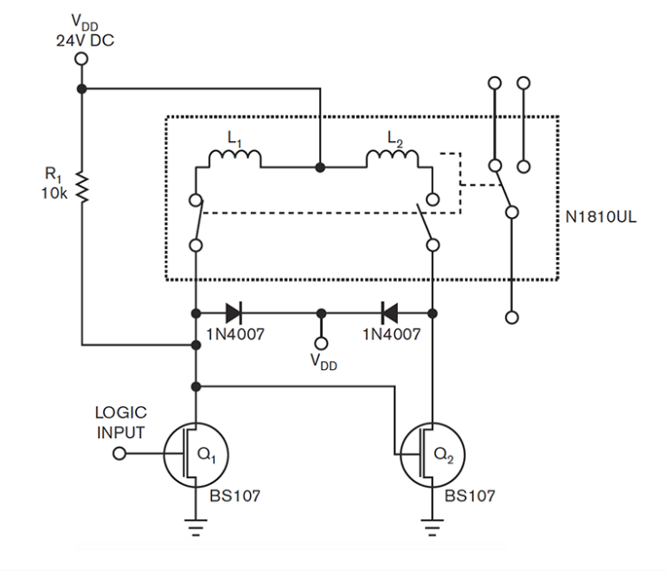
I have found the following circuit that would work for a coil that accepts continuous current, but it does not give a pulse:

enter image description here

(Note: the diodes will not be required because my relay has internal flyback diodes).

Simply adding a capacitor between the voltage supply and the coils would give a pulse but there would be no way for it to discharge.

I would also consider some kind of IC if that is required but would like to avoid an IC.

I would be grateful for any suggestions.

\$\endgroup\$
4
  • \$\begingroup\$ You need to describe in detail how you intend to control it and what you are trying to do . If you just disconnect Q2 gate from Q1 drain and drive the gates individually you can pulse either gate with a few tens of milleconds pulse (whatever the relay requires), but I suspect that is not helpful. \$\endgroup\$ Commented Jul 13, 2022 at 12:23
  • \$\begingroup\$ Thank you Spehro. I have a commercial BMS for a lithium battery bank on a boat. The BMS puts out a steady 12v (not a pulse) to energize a conventional electromechanical contactor and puts out 0v to de-energize the contactor. I want to replace the contactor with the latching relay (which I already have) in order to save the power wasted in holding the contactor closed. \$\endgroup\$
    – andy_r
    Commented Jul 13, 2022 at 13:28
  • \$\begingroup\$ So, what I need is a circuit that will send a single pulse to the set pin on the relay whenever the input goes high (12v) and a single pulse to the reset pin whenever the input goes low. The pictured circuit will send a continuous signal to the desired pin and what i need is a 15-100ms pulse. \$\endgroup\$
    – andy_r
    Commented Jul 13, 2022 at 13:33
  • \$\begingroup\$ On the surface it would seem pretty simple, a couple monostables triggered on each side of the input driving beefy MOSFETs (not those wimpy BS107s) to handle the high current (amperes) inductive loads. I would, however, worry about it getting out of sync with the input though, on startup and perhaps under other conditions. A circuit that detected a mismatch and kept trying to correct it (with a safe duty cycle for the coils) would be better. \$\endgroup\$ Commented Jul 13, 2022 at 15:19

2 Answers 2

1
\$\begingroup\$

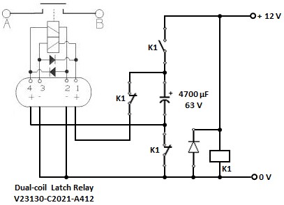
A standard 3PDT electromagnetic relay, an electrolytic capacitor and a freewheeling diode would be required.

Here's the schematic.

enter image description here

\$\endgroup\$
4
  • \$\begingroup\$ vu2nan: Thank you for answering. I am sorry, but I am very inexperienced and I do not understand this circuit. Could I trouble you to tell me what each of the four K1s represent? \$\endgroup\$
    – andy_r
    Commented Jul 13, 2022 at 22:38
  • \$\begingroup\$ Hi Andy, Rectangle 'K1' is the relay coil. Uppermost 'K1' is the 'normally-open' (NO) contact and the other two 'normally-closed' (NC). When the relay coil is energised, the 'NC' contacts will open first and then the 'NO' contacts will close. Likewise, when the relay coil is de-energised, the 'NO' contacts will open first and then the 'NC' contacts will close. Thus, when relay 'K1' is energised, the capacitor charge-pulse will 'set' the latch relay and close contact 'AB'. When relay 'K1' is de-energised, the capacitor discharge-pulse will 'reset' the latch relay and open contact 'AB'. \$\endgroup\$
    – vu2nan
    Commented Jul 14, 2022 at 4:15
  • \$\begingroup\$ @vu2nan How did you size the capacitor? \$\endgroup\$
    – ARF
    Commented Sep 10, 2022 at 10:36
  • 1
    \$\begingroup\$ @ARF - Time constant RC (with coil resistance 4.7 Ω & capacitance 4700 μF) = 4.7 * 4700 / 1000 = 22 ms \$\endgroup\$
    – vu2nan
    Commented Sep 11, 2022 at 3:01
0
\$\begingroup\$

The trick to using a capacitor is simple: a push-pull driver. Any little H-bridge IC will do. Even the old ones without current limiting.

\$\endgroup\$

Your Answer

By clicking “Post Your Answer”, you agree to our terms of service and acknowledge you have read our privacy policy.

Not the answer you're looking for? Browse other questions tagged or ask your own question.