0
\$\begingroup\$

Background

I have the following circuit and it has been working for years. Please note that the circuit drawing may not match the real circuit exactly, but it is just a diagram to attempt to get my point across.
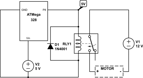
schematic

simulate this circuit – Schematic created using CircuitLab

Diagram Main Point

I have a 5V input driving a 12V output circuit. When the code makes the Arduino set P8 high then the relay is activated and the 12V circuit is turned on which powers a motor.

Since it is only 12V on the output circuit I'm guessing that there is a way to replace the relay (which is rated for up to 120V) with a simply BJT (or your suggestion).

Specific Transistor

I mention a BJT, because I am curious if a 2N2222 NPN transistor could be used to replace it. The circuit is 12V but the CE max voltage of that transistor is 40V. Also mentioning because I have immediate availability on those.

Questions

  1. Is it even feasible that the 2N2222 could be used? If not, why not?
  2. What you would suggest as the optimal (solid state) replacement for the relay?
\$\endgroup\$
8
  • \$\begingroup\$ Your circuit isn't drawn correctly, can you edit it please? If you're having trouble with that let me know and I can have a go at it. \$\endgroup\$
    – GodJihyo
    Commented Jul 14, 2022 at 13:15
  • \$\begingroup\$ @GodJihyo It's probably that part on the relay magnet side, right? I'm using a very simple device (see this: amzn.to/3RxPQFR ) that makes wiring it up in real life very easy but I've probably drawn it improperly. Please fix it. I appreciate your help. \$\endgroup\$
    – raddevus
    Commented Jul 14, 2022 at 13:18
  • \$\begingroup\$ Okay. Can you also tell us what motor you are using as that would tell us what would be needed to drive it. \$\endgroup\$
    – GodJihyo
    Commented Jul 14, 2022 at 13:21
  • 1
    \$\begingroup\$ Schematic edited. \$\endgroup\$
    – GodJihyo
    Commented Jul 14, 2022 at 13:52
  • 1
    \$\begingroup\$ How many amps the motor needs? If you know that you can find a transistor capable of thay many amps. \$\endgroup\$
    – Justme
    Commented Jul 14, 2022 at 17:50

4 Answers 4

2
\$\begingroup\$

You can replace the relay with a transistor, the type of transistor would depend on the current draw of the motor.

A bipolar transistor can be used, but more often these days you'll see a MOSFET used.

You can read about MOSFETs as switches here. Note the use of a flyback diode or 'snubber' network when switching an inductive load.

\$\endgroup\$
1
\$\begingroup\$

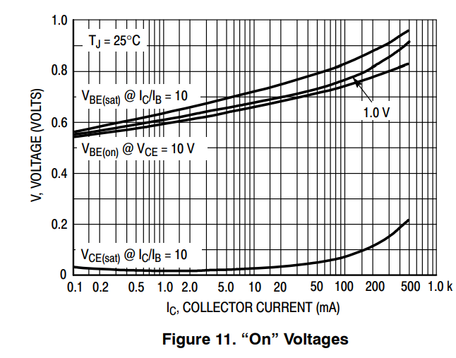
Always study the datasheets! On the first page of the 2N2222A datasheet, under Absolute Maximums, you'll see that the 2n2222A has a max of 600mA. enter image description here But we have to remember that's an absolute maximum, which means under normal conditions, this transistor will never be able to handle that much current. If you scroll down some more, they always provide handy graphs for you. In this one, we can see that this transistor is more meant for 100-200mA max. enter image description here

You'll need to look into MOSFETs. MOSFETs will allow you to switch much higher currents from a 5V GPIO pin. You'll want to find a TTL MOSFET, these works with lower "turn on" voltages (5V from a GPIO). You can find hundreds of tutorials online, here's just one for reference.

Good luck!

\$\endgroup\$
1
  • 1
    \$\begingroup\$ Thank you for pointing me to the MOSFET and for explaining the current handling ability. I will look into the MOSFET. I'll wait a bit but then mark this as the answer since it explains why and the alternative I should use. \$\endgroup\$
    – raddevus
    Commented Jul 14, 2022 at 14:03
1
\$\begingroup\$

I think you would need to place the transistor on the low side of your motor, connecting the return path of your motor to the voltage source return. Then drive the gate/base of the transistor with your 5V P8 pin.

I imagine you would need to add some protection across the transistor not to exceed the drain to source or collector to emitter voltage rating with inductive spikes.

\$\endgroup\$
1
\$\begingroup\$

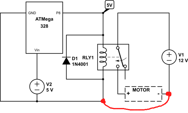
Can you make the following connection?

Example schematic with ground link added

If so, then a level shift and high-side switch can be used, or if the switch and motor can swap position, a low-side switch can be used.

Whether any particular transistor is suitable cannot be determined without motor ratings.

\$\endgroup\$

Your Answer

By clicking “Post Your Answer”, you agree to our terms of service and acknowledge you have read our privacy policy.

Not the answer you're looking for? Browse other questions tagged or ask your own question.