I am attempting to connect a DMM-4026-B-I2S-EB-R to an ESP32-S2-DevKitC.
I am writing this code in the Arduino IDE. It is based on the code from this article.
I believe my code works; I included it anyway.
/*
  ESP32 I2S Microphone Sample
  esp32-i2s-mic-sample.ino
  Sample sound from I2S microphone, display on Serial Plotter
  Requires INMP441 I2S microphone

  DroneBot Workshop 2022
  https://dronebotworkshop.com
*/

// Include I2S driver
#include <driver/i2s.h>

#define I2S_WS 4
#define I2S_SD 5
#define I2S_SCK 18

// Use I2S Processor 0
#define I2S_PORT I2S_NUM_0

// Define input buffer length
#define bufferLen 64
int16_t sBuffer[bufferLen];

void i2s_install() {
  // Set up I2S Processor configuration
  const i2s_config_t i2s_config = {
    .mode = i2s_mode_t(I2S_MODE_MASTER | I2S_MODE_RX),
    .sample_rate = 44100,
    .bits_per_sample = I2S_BITS_PER_SAMPLE_16BIT,
    .channel_format = I2S_CHANNEL_FMT_ONLY_LEFT,
    .communication_format = I2S_COMM_FORMAT_STAND_I2S,
    .intr_alloc_flags = 0,
    .dma_buf_count = 8,
    .dma_buf_len = bufferLen,
    .use_apll = false
  };

  esp_err_t debug1 = i2s_driver_install(I2S_PORT, &i2s_config, 0, NULL);
  Serial.print("Driver is: ");
  Serial.println(debug1);
}

void i2s_setpin() {
  // Set I2S pin configuration
  const i2s_pin_config_t pin_config = {
    .bck_io_num = I2S_SCK,
    .ws_io_num = I2S_WS,
    .data_out_num = I2S_PIN_NO_CHANGE,
    .data_in_num = I2S_SD
  };

  esp_err_t debug2 = i2s_set_pin(I2S_PORT, &pin_config);
  Serial.print("RESULT OF SET PIN:");
  Serial.println(debug2);
}

void setup() {

  // Set up Serial Monitor
  Serial.begin(115200);
  Serial.println(" ");

  delay(1000);

  // Set up I2S
  i2s_install();
  i2s_setpin();
  i2s_start(I2S_PORT);
  i2s_set_clk(I2S_PORT, 22050,  I2S_BITS_PER_SAMPLE_16BIT, I2S_CHANNEL_MONO);

  delay(500);
}

void loop() {

  // False print statements to "lock range" on serial plotter display
  // Change rangelimit value to adjust "sensitivity"


  // Get I2S data and place in data buffer
  size_t bytesIn = 0;
  esp_err_t result = i2s_read(I2S_PORT, &sBuffer, bufferLen, &bytesIn, portMAX_DELAY);

  if (result == ESP_OK) {
    Serial.print("READ IS: ");
    Serial.println(result);
    // Read I2S data buffer
    int16_t samples_read = bytesIn / 8;
    if (samples_read > 0) {
      float mean = 0;
      for (int16_t i = 0; i < samples_read; ++i) {
        mean += (sBuffer[i]);
      }

      // Average the data reading
      mean /= samples_read;

      // Print to serial plotter
      Serial.println(mean);
    }
  }
  else
  {
    Serial.println(result);
  }
}
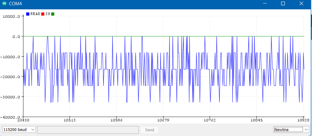
The microphone worked exactly once. Now, the microphone outputs random, but seemingly periodic values.
Note the output here is all negative. The one time it worked, the output created an almost sine-wave-like graph, ranging from positive to negative.
This output continues even if ground is disconnected from the dev board or 3V3 is disconnected from the dev board, but not both.
Here is the output from the Serial Monitor:
-20479.50
READ IS: 0
-24575.00
READ IS: 0
-16384.00
READ IS: 0
-24576.00
READ IS: 0
-24576.00
READ IS: 0
-32768.00
READ IS: 0
-12287.00
READ IS: 0
-20480.00
READ IS: 0
-16384.00
READ IS: 0
-16384.00
READ IS: 0
-4096.00
READ IS: 0
-12288.00
READ IS: 0
-8191.00
READ IS: 0
-16383.00
READ IS: 0
-4096.00
READ IS: 0
-12288.00
READ IS: 0
-16384.00
READ IS: 0
-12287.00
READ IS: 0
-12287.00
READ IS: 0
-8191.00
READ IS: 0
-4095.00
READ IS: 0
-28671.00
My question is: What is the most likely cause of this microphone breakout board not working?
My thinking is that, based on this info, the microphone breakout board did not start up properly. Furthermore, since it did work once, this would tell me the board did not start up properly due to a connection issue. However, I am unsure how to determine which connection is bad, or if that is the problem at all.
- I have checked the Espressif API reference for the S2
- I have checked connections, but only with an analog multimeter, perhaps there could still be an issue with a connection due to my poor soldering.
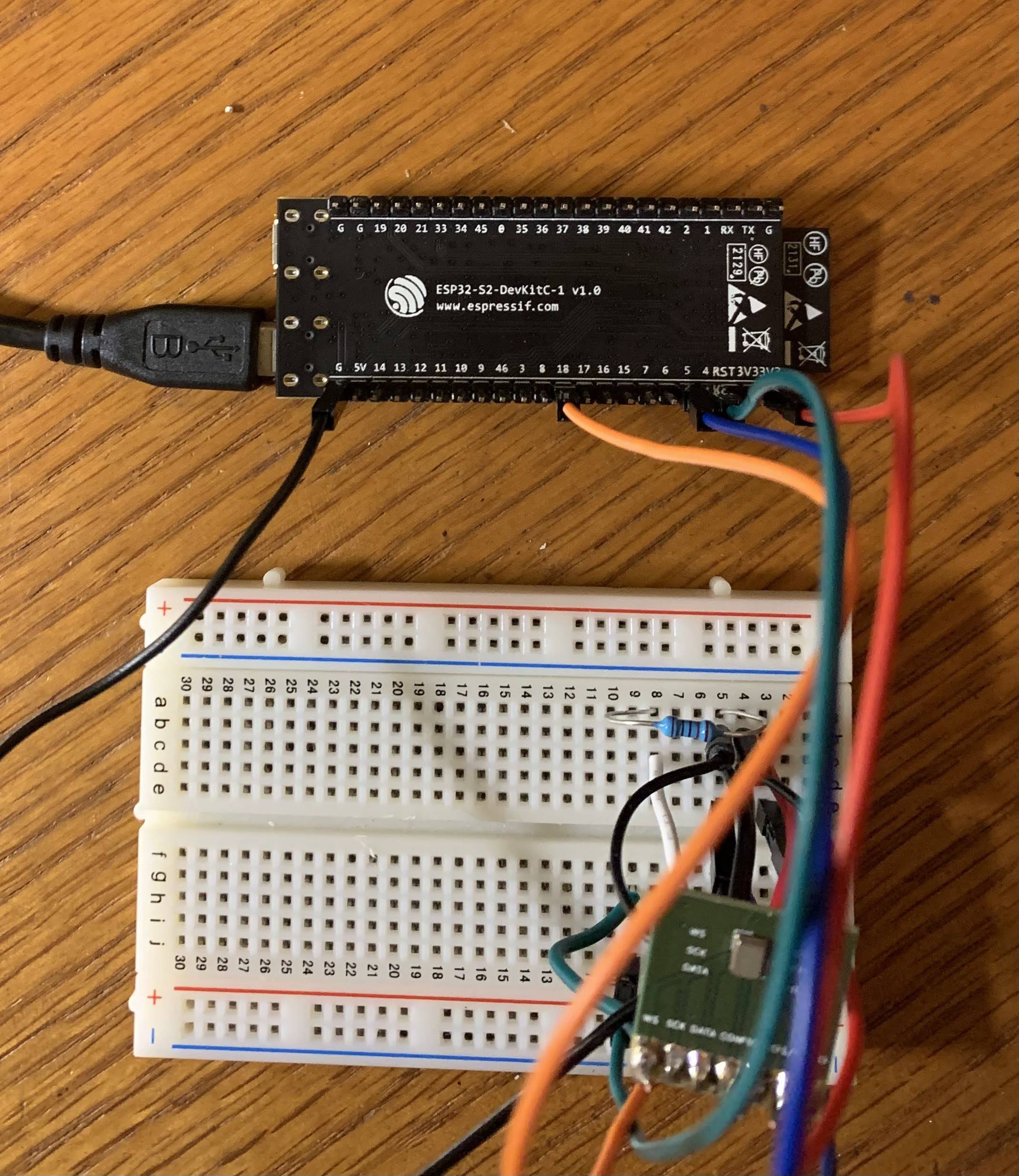
Here is a picture of the circuit:
The config pin has a 10 kΩ pull down resistor. The L/R pin is connected to ground.
The only tools I have available are a soldering iron and an analog multimeter.
Related questions:
- Digital Microphone : I2S data output Similar sounding issue, however, no accepted answer, and the answers given do not help.


