1
\$\begingroup\$

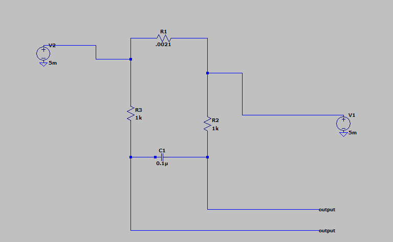
Has anyone ever dealt with a circuit similar to the one I have? It is a current sensing circuit but I do not understand how it works. I believe there will be a voltage difference between my R2 and R3; if that is the case can someone explain why that is?

I am having hard time tracing to the output. The current experienced by each resistor will result in voltage drops but any help with walking through this circuit would be helpful. I get lost trying to trace the current paths given two power supplies.

\$\endgroup\$
3
  • \$\begingroup\$ Are you sure the wires labeled "output" are not the input? \$\endgroup\$ Commented Aug 23, 2022 at 0:02
  • \$\begingroup\$ Also, if both are labeled "output", they will be connected together, and will never register a voltage. \$\endgroup\$
    – PStechPaul
    Commented Aug 23, 2022 at 0:09
  • \$\begingroup\$ No , they are outputs connected to an OP amp. Vir below was right in his assessment . The amplifier does have high input impedance \$\endgroup\$
    – Jay
    Commented Aug 23, 2022 at 4:54

3 Answers 3

3
\$\begingroup\$

With the values shown there will be no output voltage if both outputs have identical loading.

You have two equal voltage sources. Neither shows any internal resistance. The voltage across R1 would be the difference of V1 and V2 which would be 5 mV - 5 mV = 0 V.

If you change one of the voltage sources the voltage across the outputs would be the difference between the voltages. The current through R1 would be this voltage divided by the value of R1.

Perhaps you meant to have one voltage source and a load, in this case the current through R1 would depend on the voltage and load, and you would be able to find the load current by measuring the voltage across the outputs and dividing by the value of R1.

\$\endgroup\$
2
  • \$\begingroup\$ Yes I probably should of put different values for V1 and V2. The values I would typically see are within a range so they will never be equal. \$\endgroup\$
    – Jay
    Commented Aug 23, 2022 at 4:55
  • \$\begingroup\$ @jay what is the actual purpose of the circuit? Why would you have two voltage sources connected like that? \$\endgroup\$
    – GodJihyo
    Commented Aug 23, 2022 at 17:19
1
\$\begingroup\$

I have used a circuit like this. R1 is a current measuring shunt. The output goes to a measuring instrument such as a voltmeter. R2, R3, C1 are a filter so the voltmeter doesn't see any noise present. This is more important when the distance from the shunt and the measuring device is far.

Why resistors on both legs? If the shunt is on the high side they offer some protection against shorts melting your wires.

\$\endgroup\$
1
\$\begingroup\$

R1 is your actual sensing element; the current flowing between V1 and V2 develops the voltage Isense*R1. R2, R3, and C1 filter out higher-frequency noise on the output. They will not appreciably affect the measured voltage if the sensing device (probably an instrumentation amplifier or something similar) has high input impedance.

\$\endgroup\$
2
  • 2
    \$\begingroup\$ (V1-V2)/R1 would give you a current, not a voltage. \$\endgroup\$
    – GodJihyo
    Commented Aug 22, 2022 at 22:54
  • \$\begingroup\$ Good catch; fixed. \$\endgroup\$
    – vir
    Commented Aug 23, 2022 at 16:42

Your Answer

By clicking “Post Your Answer”, you agree to our terms of service and acknowledge you have read our privacy policy.

Not the answer you're looking for? Browse other questions tagged or ask your own question.